Method and apparatus for plasma forming inner magnetic bucket to control a volume of a plasma

a technology of plasma and inner magnetic bucket, which is applied in the direction of plasma technique, chemical vapor deposition coating, coating, etc., can solve the problems of reducing substrate throughput, adding costs due to production loss, and particle contamination inside the process chamber, so as to improve the operation of the substrate processing system and reduce damage and/or cleaning problems.

Inactive Publication Date: 2006-06-27
LAM RES CORP
View PDF36 Cites 43 Cited by
  • Summary
  • Abstract
  • Description
  • Claims
  • Application Information

AI Technical Summary

Benefits of technology

[0022]The magnetic field establishes a containment field (a type of “magnetic wall”) within the chamber. The containment field can be shifted in a preselected manner to improve operation of the substrate processing system and to reduce the damage and / or cleaning problems caused by the plasma's interaction with other elements of the processing system. Shifting of the containment field can be accomplished by moving the magnetic array. Movement may be continuous (that is, spinning or translating one or more magnet elements) or incremental (that is, periodically shifting the position of one or more magnet elements).

Problems solved by technology

If the plasma reaches non-active regions of the chamber wall, etch, deposition, and / or corrosion of the areas may ensue, which may lead to particle contamination inside the process chamber, i.e., by etching the area or flaking of deposited material.
Cleaning disadvantageously lowers substrate throughput, and typically adds costs due to loss of production.
In systems using a larger gap between the substrate and the RF source, even greater plasma interaction and hence particle losses to the wall occur.
Such increased power leads to higher electron temperatures in the plasma and, consequently, leads to potential damage of the substrate and the chamber wall as well.

Method used


Image

  • Method and apparatus for plasma forming inner magnetic bucket to control a volume of a plasma
  • Method and apparatus for plasma forming inner magnetic bucket to control a volume of a plasma
  • Method and apparatus for plasma forming inner magnetic bucket to control a volume of a plasma

Examples


Embodiment Construction

[0031]The present invention will now be described in detail with reference to a few preferred embodiments thereof and as illustrated in the accompanying drawings. In the following description, numerous specific details are set forth in order to provide a thorough understanding of the present invention. It will be obvious, however, to one skilled in the art, that the present invention may be practiced without some or all of these specific details. In other instances, well known process steps have not been described in detail to avoid obscuring the present invention.

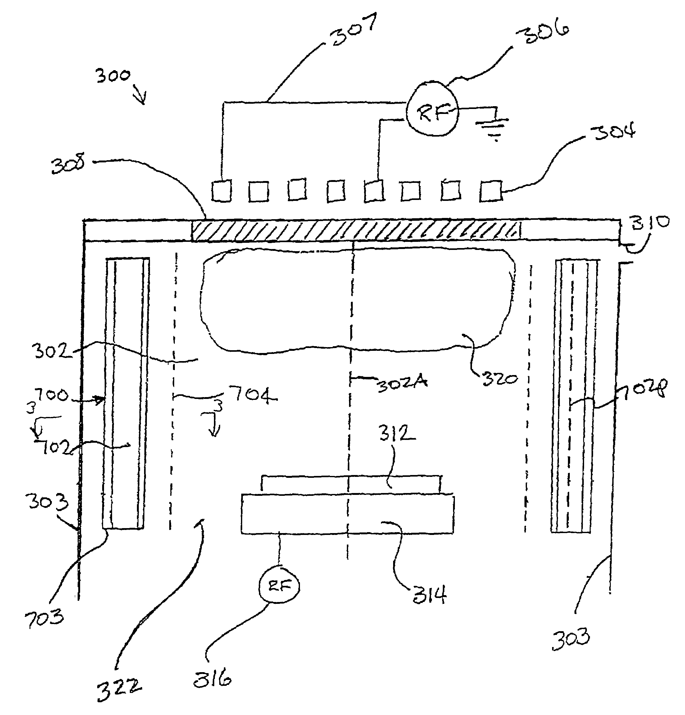
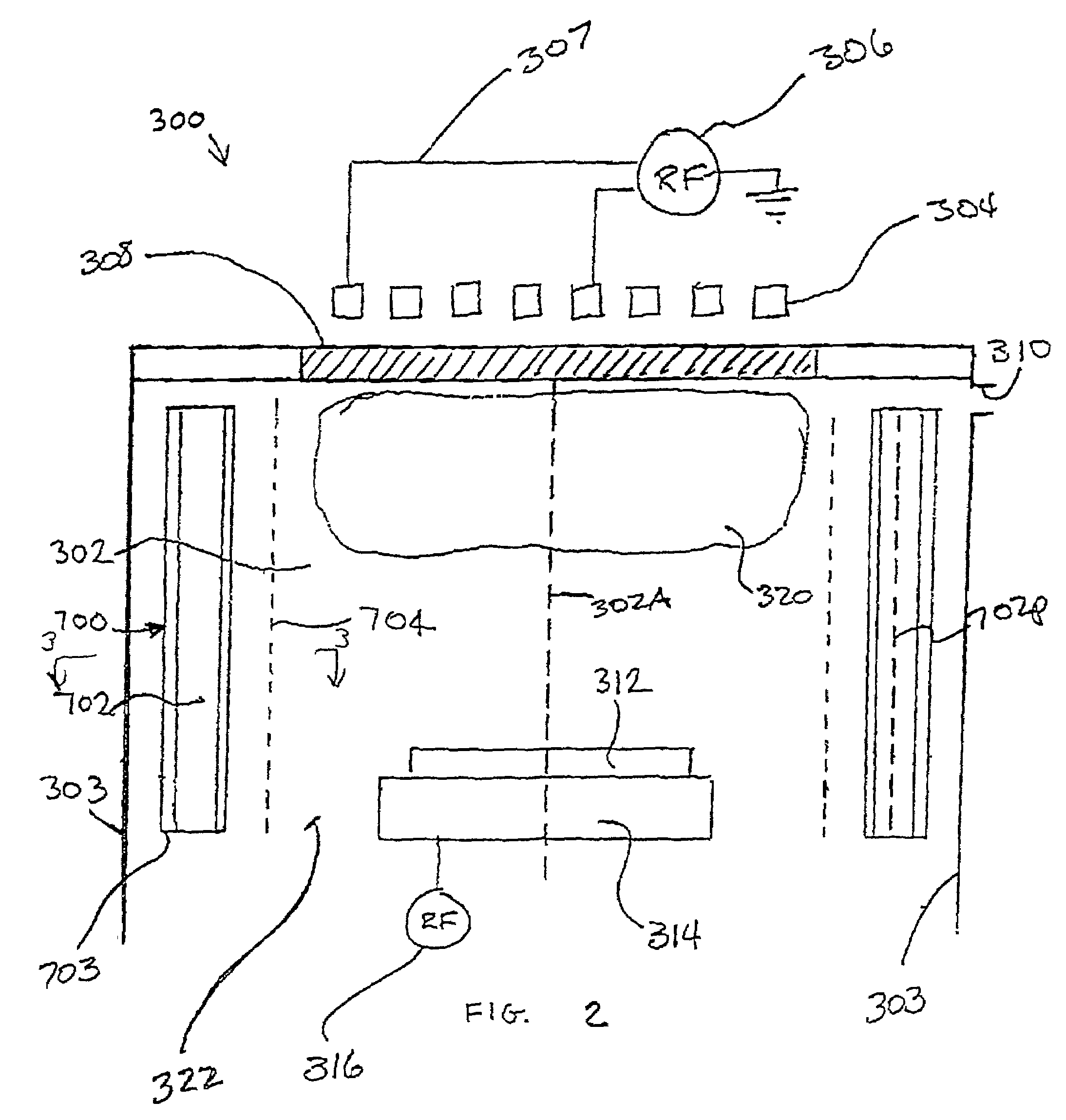
[0032]In one embodiment, the present invention provides a plasma processing apparatus for processing a substrate. The plasma processing apparatus includes a substantially cylindrical process chamber, defined at least in part by a wall, within which a plasma is both ignited and sustained for processing the substrate. The plasma processing apparatus further includes a plasma confinement arrangement being configured with a ma...


PUM

PropertyMeasurementUnit
frequencyaaaaaaaaaa
radiiaaaaaaaaaa
plasmaaaaaaaaaaa

Abstract

A plasma confinement arrangement for controlling the volume of a plasma while processing a substrate inside a process chamber includes a chamber within which a plasma is both ignited and sustained for processing. The chamber is defined at least in part by a wall and further includes a plasma confinement arrangement. The plasma confinement arrangement includes a magnetic array disposed inside of the chamber. The magnetic array has a plurality of magnetic elements that are disposed around a plasma region within the process chamber.

Description

CROSS-REFERENCE TO RELATED CASES[0001]This application is related to the following commonly assigned U.S. Patent Applications:[0002]Application Ser. No. 09 / 439,759 entitled METHOD AND APPARATUS FOR CONTROLLING THE VOLUME OF A PLASMA,[0003]Application Ser. No. 09 / 439,661 entitled IMPROVED PLASMA PROCESSING SYSTEMS AND METHODS THEREFOR.[0004]Application Ser. No. 09 / 470,236 entitled PLASMA PROCESSING SYSTEM WITH DYNAMIC GAS DISTRIBUTION CONTROL,[0005]Application Ser. No. 09 / 439,675 entitled TEMPERATURE CONTROL SYSTEM FOR PLASMA PROCESSING APPARATUS,[0006]Application Ser. No. 09 / 440,418 entitled METHOD AND APPARATUS FOR PRODUCING UNIFORM PROCESS RATES,[0007]Application Ser. No. 09 / 440,794 entitled MATERIALS AND GAS CHEMISTRIES FOR PLASMA PROCESSING SYSTEMS,[0008]Application No. 09 / 536,000 entitled METHOD AND APPARATUS FOR CONTROLLING THE VOLUME OF A PLASMA, filed on even date herewith[0009]Each of the above-identified patent applications is incorporated herein by reference.BACKGROUND OF...

Claims


Application Information

Patent Timeline
Patent Type & Authority Patents(United States)
IPC IPC(8): C23F1/00C23C16/00H01L21/306H01J37/32
CPCH01J37/321H01J37/32688H01J37/32623H05H1/16
Inventor BAILEY, III, ANDREW D.
Owner LAM RES CORP
Why Eureka
Try Eureka