
Tape carrier package and method of fabricating the same

Inactive Publication Date: 2006-06-27
LG DISPLAY CO LTD
View PDF10 Cites 9 Cited by
  • Summary
  • Abstract
  • Description
  • Claims
  • Application Information

AI Technical Summary

Benefits of technology

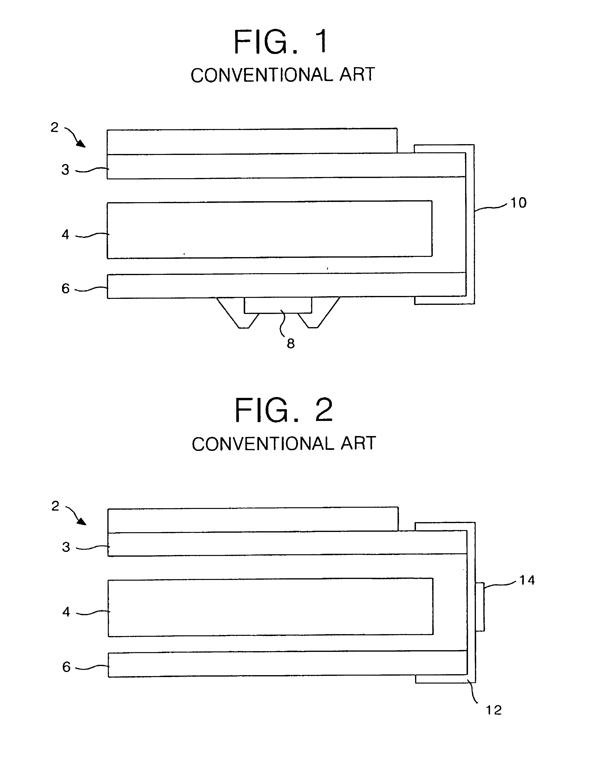
[0019]FIG. 1 is a sectional view showing an integrated circuit mounting method employing the conventional chip on board system;
[0020]FIG. 2 is a sectional view showing an integrated circuit mo

Problems solved by technology

Accordingly, significantly bad alignments may be produced in the process of adhering the TCP to the PWB.
Also, since the liquid crystal panel made from a glass transmits light even after the adhesion of the TCP to the PWB, alignment can be confirmed using a microscope; whereas, since the PWB does not transmit light, alignment cannot be confirmed using a microscope.
However, this method is complicated and unable to accurately determine an alignment.
Also, such a method is time consuming.

Method used


Image

  • Tape carrier package and method of fabricating the same
  • Tape carrier package and method of fabricating the same
  • Tape carrier package and method of fabricating the same

Examples


Embodiment Construction

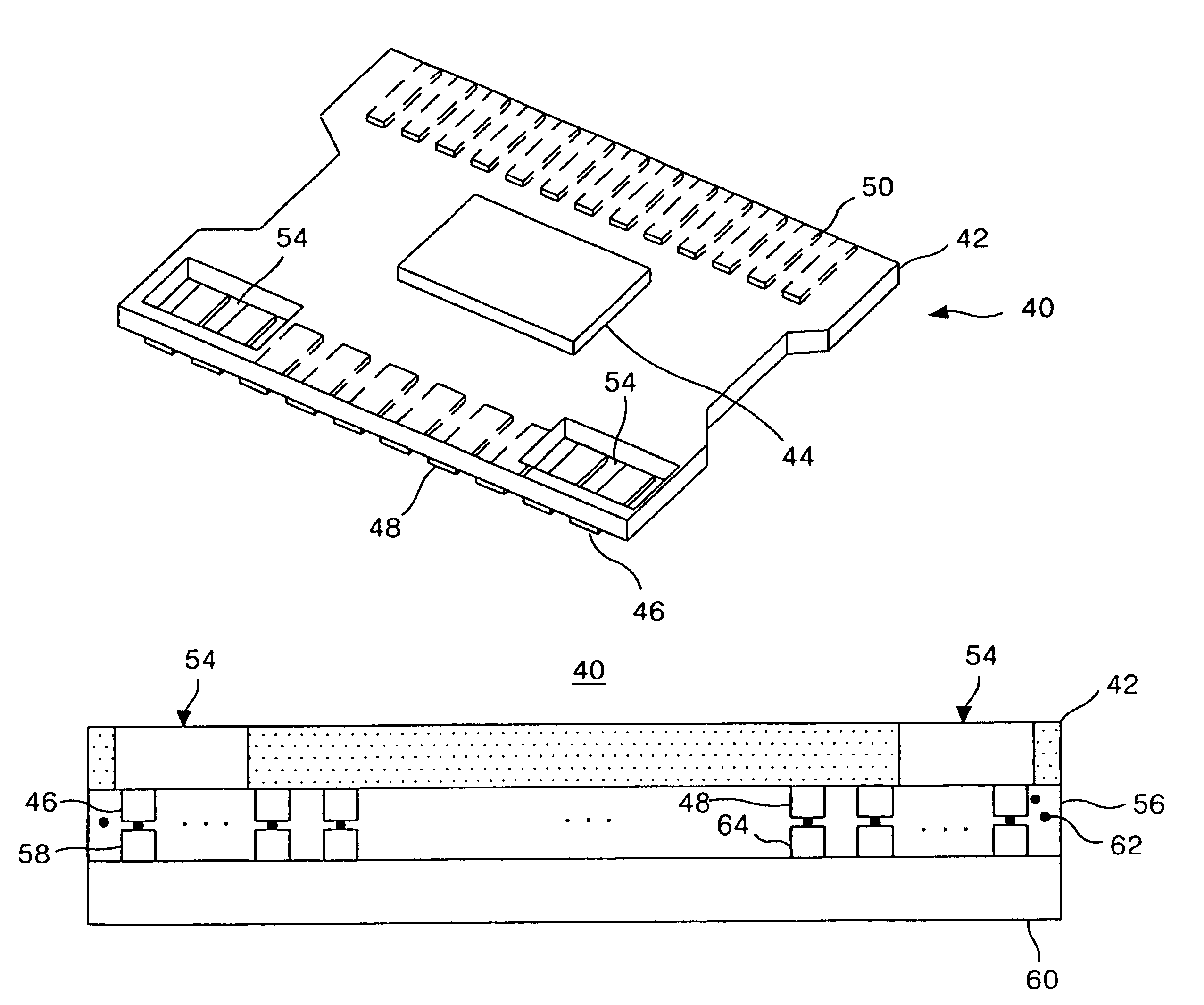
[0026]Referring to FIG. 6, there is shown a tape carrier package (TCP) according to an embodiment of the present invention. The TCP 40 includes a base film 42, ICs 44 mounted on the base film 42, input and output pads 48 and 50 connected to the input and output pins of the ICs 44 and formed on the base film 42, dummy pads 46 provided at the side end of the input pads 48, and windows 54 defined by openings in the base film 42 to confirm an alignment of the dummy pads 46. The input and output pads 48 and 50 have a two-layer structure in which copper(Cu) is plated with tin(Sn) for preventing oxidation, and are fixed onto the base film 42 with a bonding layer. For example, the dummy pads 46 are formed five by five at the left and right side of the input pads 48. The windows 54 are formed into a square shape by punching the base film 42 provided with the dummy pads 46. The windows 54 are punched into such a desired size that alignment between the first two or three dummy lines 46 can be ...


PUM


Abstract

A tape carrier package with a widow that is capable of confirming an alignment extent between the tape carrier package and a print wiring board in bonding the tape carrier package mounted with an integrated circuit on the liquid crystal panel and the print wiring board. In the package, the integrated circuit is mounted onto a base film. Input pads are connected to the integrated circuit and formed on the base film. Dummy pads are formed at the left and right side thereof not to be connected to the integrated circuit. Windows are provided by opening the base film adjacent to the dummy pads to expose at least two of said dummy pads.

Description

[0001]This Application is a Divisional Application of U.S. application Ser. No. 09 / 585,439, filed on Jun. 2, 2000, now U.S. Pat. No. 6,559,549.BACKGROUND OF THE INVENTION[0002]This application claims benefit of Korean patent application number P2000-0866, filed Feb. 23, 2000, which is hereby incorporated by reference for all purposes as if fully set forth herein.[0003]1. Field of the Invention[0004]This invention relates to a tape carrier package for mounting an integrated circuit and a liquid crystal display containing the same, and more particularly to a tape carrier package with a window through which an alignment between the tape carrier package and a printed wiring board can be confirmed with the naked eye.[0005]2. Description of the Related Art[0006]Generally, an active matrix liquid crystal display uses thin film transistors (TFTs) as switching devices to display a natural-looking moving picture. Since such a liquid crystal display device can be made into a smaller-size devic...

Claims


Application Information

Patent Timeline
IPC IPC(8): H01L21/50G02F1/13H01L23/498H01L23/544H05K3/32H05K3/36
CPCH01L23/4985H01L23/544H05K3/361H01L2223/54473H05K3/323H05K2201/0394H01L2924/0002H05K2201/09781Y10S438/975H01L2924/00G02F1/13
Inventor CHO, HYOUNG SOO
Owner LG DISPLAY CO LTD
Learn More