Piezoelectric diaphragm and piezoelectric electroacoustic transducer using the same

a technology of piezoelectric electroacoustic transducer and diaphragm, which is applied in the direction of piezoelectric/electrostrictive/magnetostrictive devices, electrical transducers, piezoelectric/electrostriction/magnetostriction machines, etc., can solve the problem of reducing the thickness of the multi-layer ceramic body b>41/b>, and the diaphragm is easily broken. problem

Inactive Publication Date: 2006-06-27
MURATA MFG CO LTD
View PDF11 Cites 1 Cited by
  • Summary
  • Abstract
  • Description
  • Claims
  • Application Information

AI Technical Summary

Benefits of technology

[0012]In order to overcome the problems described above, preferred embodiments of the present invention provide a piezoelectric diaphragm having reliable electrical connections between a side surface electrode and upper and lower principal-surface electrodes and having improved resistance against mechanical shocks, and also provide a piezoelectric electroacoustic transducer including such a novel piezoelectric diaphragm.

Problems solved by technology

However, because this piezoelectric diaphragm is made of only ceramic layers, the piezoelectric diaphragm is easily broken when a mechanical shock such as a drop impact is applied to it.
This problem becomes more serious, in particular, when the thickness of the multilayer ceramic body 41 is reduced.

Method used


Image

  • Piezoelectric diaphragm and piezoelectric electroacoustic transducer using the same
  • Piezoelectric diaphragm and piezoelectric electroacoustic transducer using the same
  • Piezoelectric diaphragm and piezoelectric electroacoustic transducer using the same

Examples


Embodiment Construction

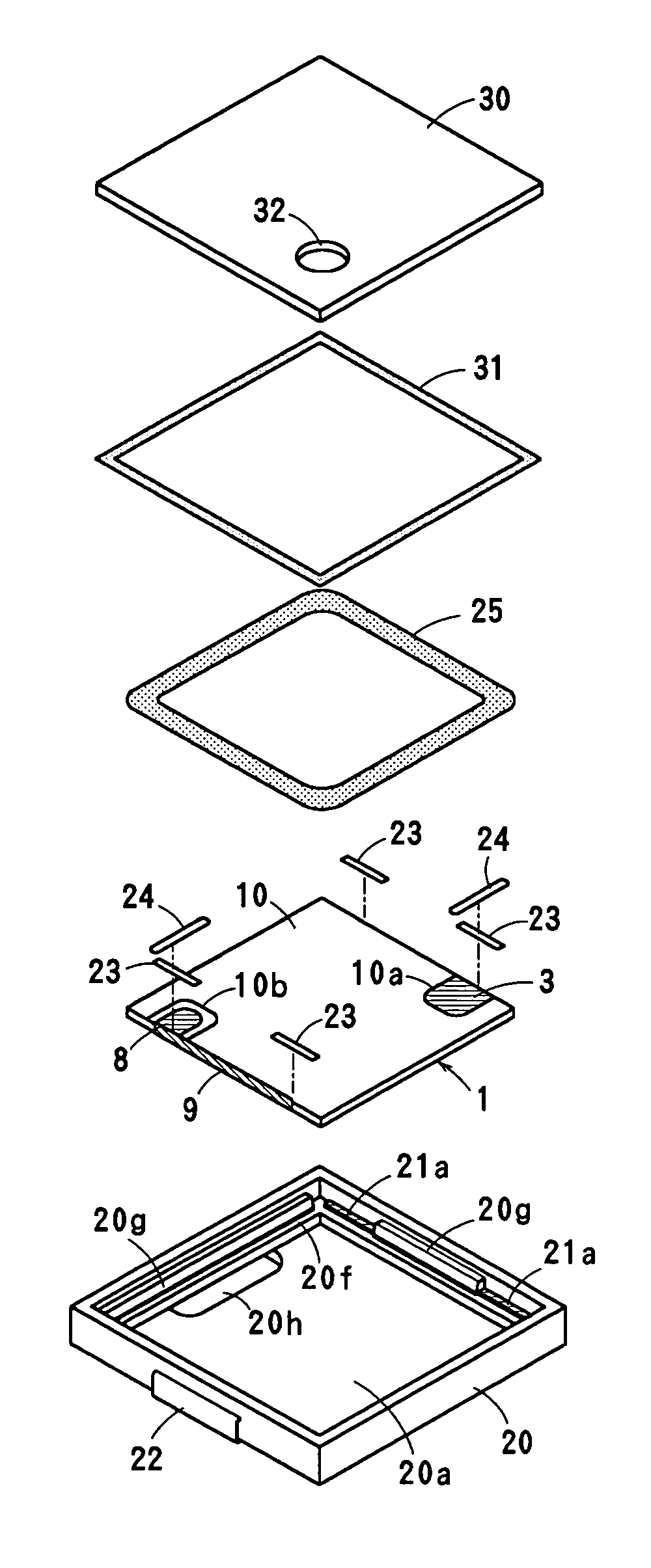
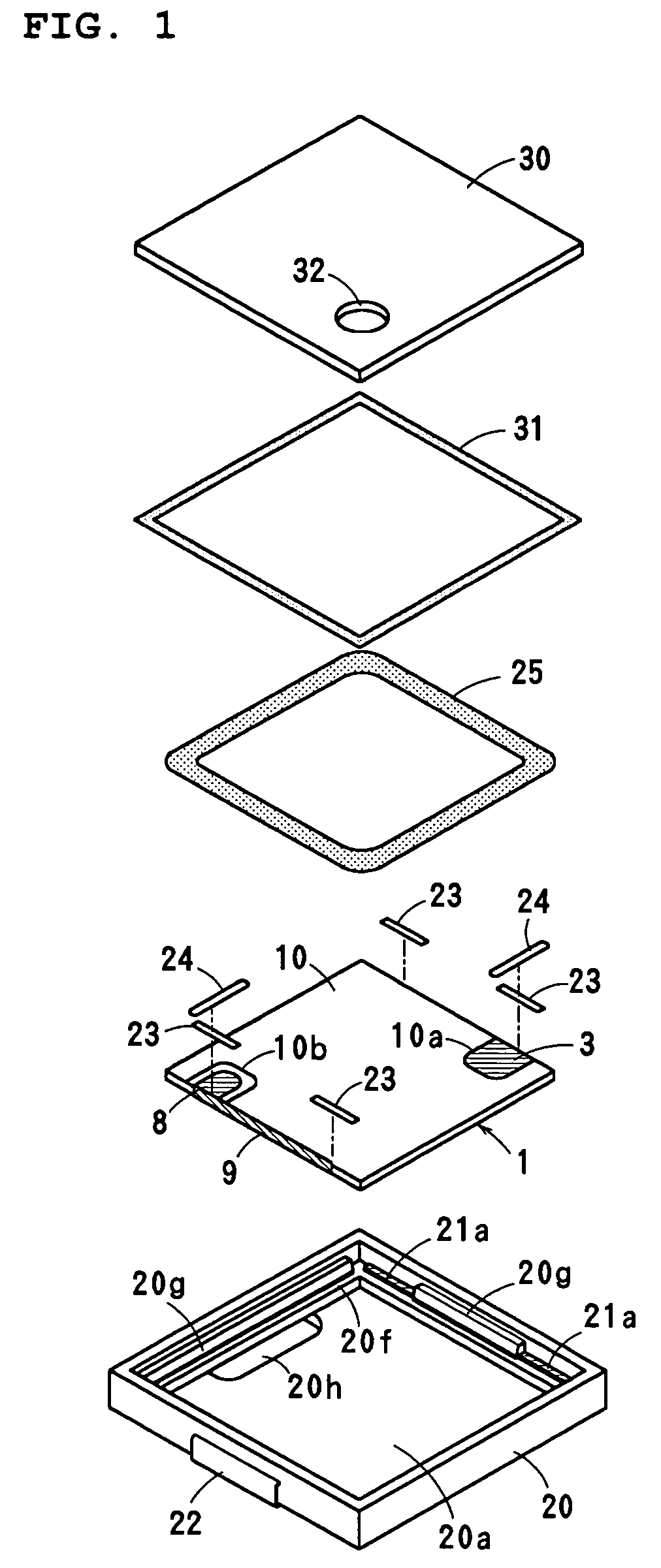
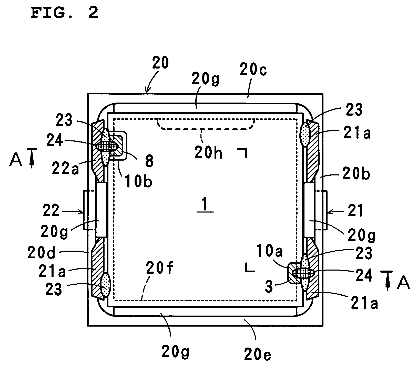
[0031]FIGS. 1 to 3 show a piezoelectric electroacoustic transducer of the surface mounting type according to a first preferred embodiment of the present invention.

[0032]This electroacoustic transducer according to the present preferred embodiment is suitable for use in applications such as a piezoelectric receiver in which the electroacoustic transducer needs to operate over a wide frequency range. The electroacoustic transducer includes a piezoelectric diaphragm 1, a case 20, and a lid 30. The case 20 and the lid 30 define a housing.

[0033]As shown in FIGS. 4 to 6, the piezoelectric diaphragm 1 includes a substantially rectangular-shaped multilayer ceramic body 2 that is preferably formed by laminating two piezoelectric ceramic layers 2a and 2b, although more layers may be used. Principal-surface electrodes 3 and 4 are disposed on upper and lower principal surfaces of the multilayer ceramic body 2. An internal electrode 5 and a dummy electrode 6 is disposed between the ceramic layer...


PUM

PropertyMeasurementUnit
Young's modulusaaaaaaaaaa
thicknessaaaaaaaaaa
thicknessaaaaaaaaaa

Abstract

A piezoelectric diaphragm has principal-surface electrodes formed on upper and lower principal surfaces of a multilayer ceramic body. An internal electrode is disposed in an interface between adjacent piezoelectric ceramic layers. The upper and lower principal surfaces of the multilayer ceramic body are substantially entirely covered with a resin layer. A first cutout is formed in a side-edge portion, along the first side surface electrode, of the upper resin layer such that the upper principal-surface electrode is partially exposed in the first cutout. A second cutout is formed in a side-edge portion, along the first side surface electrode, of the lower resin layer such that the lower principal-surface electrode is partially exposed in the second cutout. The locations of the first and second cutouts formed in the upper and lower resin layers, respectively, are selected such that they do not oppose each other.

Description

BACKGROUND OF THE INVENTION[0001]1. Field of the Invention[0002]The present invention relates to a piezoelectric diaphragm for use in a piezoelectric receiver, a piezoelectric sounder, or other suitable apparatus, and also to a piezoelectric electroacoustic transducer including such a piezoelectric diaphragm.[0003]2. Description of the Related Art[0004]Piezoelectric electroacoustic transducers are widely used as piezoelectric sounders, piezoelectric receivers, or other elements in electronic devices, home electronic appliances, portable telephones, or apparatuses. In such piezoelectric electroacoustic transducers, it has been proposed in Japanese Unexamined Patent Application Publication No. 2001-95094 to use a bimorph piezoelectric diaphragm made of multilayer piezoelectric ceramic.[0005]The piezoelectric diaphragm disclosed in Japanese Unexamined Patent Application Publication No. 2001-95094 is in the form of a multilayer ceramic body produced by laminating two or three piezoelect...

Claims


Application Information

Patent Timeline
Patent Type & Authority Patents(United States)
IPC IPC(8): H01L41/08H01L41/083H01L41/09H02N2/04H04R17/00
CPCH04R17/00H01L41/0973H01L41/083H10N30/50H10N30/2047
Inventor TAKESHIMA, TETSUOTAJIMA, KIYOTAKAKOSUGI, YUJI
Owner MURATA MFG CO LTD
Why Eureka
Try Eureka