Method for recording magnetic information and magnetic recording system

a magnetic information and recording system technology, applied in special recording techniques, nanoinformatics, instruments, etc., can solve the problems of difficult voltage application to a non-wiring super high recording density medium such as an hdd, and extremely difficult to fabricate these, and achieve low power consumption and high density.

Inactive Publication Date: 2006-06-27
HITACHI LTD
View PDF17 Cites 16 Cited by
  • Summary
  • Abstract
  • Description
  • Claims
  • Application Information

AI Technical Summary

Benefits of technology

[0014]The size of the region to which the image potential is modulated can be made minute even down to the atomic level, although it depends on the distance between the probe and the surface of the medium. Writing continues until the flux reversal reaches the flux volume which is stabilized by the magnetic anisotropy of the medium. The magnetization during writing is stabilized by simultaneously applying an external magnetic field so weak that the flux reversal does not occur outside of the writing region in the same direction as the writing magnetization direction, resulting in more stable writing being possible. Moreover, it is possible to reduce the threshold of the writing electric field by applying simultaneously an electric field and an external magnetic field. This reduction of the threshold of the writing electric field can be made by heating the writing region and reducing the coercivity of the heated medium. That is, it is possible to make the magnetization stable during writing and to reduce the threshold of the writing electric field as a means for assisting the magnetization direction control of the writing region. Moreover, it is also possible to reduce the threshold of the writing electric field by using thermal assistance in which the medium is heated.
[0017]It is an object of the present invention that high density, low power consumption, and non-contact magnetic recording is carried out in a magnetic recording medium.

Problems solved by technology

In order to provide a semiconductor layer or insulator layer inside of the above-mentioned triple-layered structure of ferromagnetic metal / non-magnetic metal / ferromagnetic metal and to be possible to control the magnetization by voltage, it is necessary to control the thickness to be extremely thin, as thin as about 2 nm or less, and, in the case when a semiconductor layer is provided outside of the triple-layered structure, it is necessary to form a steep metal / semiconductor interface on the level of an atomic layer, therefore, fabricating these are extremely difficult.
Moreover, a wiring-type memory such as MRAM, which is lower density as compared to an HDD, is assumed as a medium, and it is difficult to apply a voltage to a non-wiring super high recording density medium such as an HDD.

Method used


Image

  • Method for recording magnetic information and magnetic recording system
  • Method for recording magnetic information and magnetic recording system
  • Method for recording magnetic information and magnetic recording system

Examples


embodiment 1

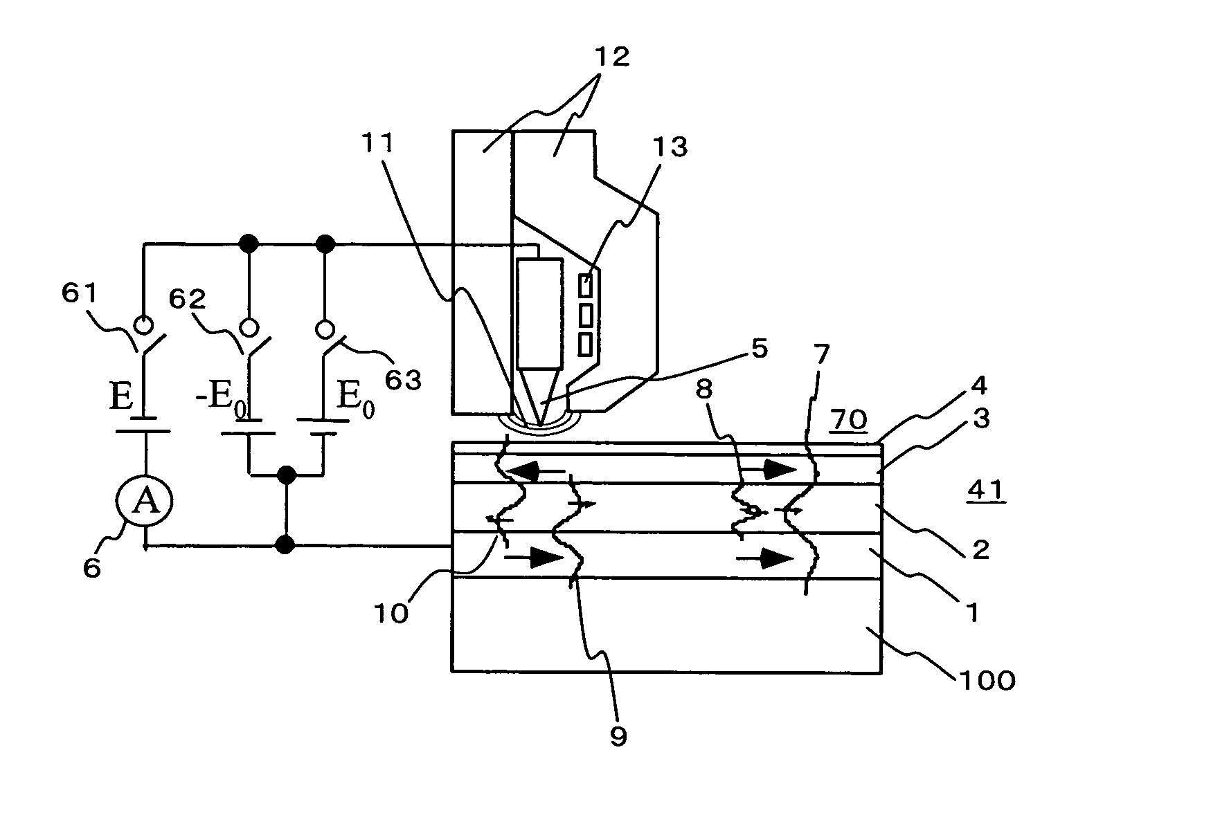
[0043]FIG. 1 is a conceptual illustration showing one example of a main part of a magnetic recording system of the present invention. The figure shows a magnetic recording medium 70, and a metallic probe 5 and a magnetic pole 12 which are provided opposite it. The magnetic recording medium 70 consists of a multilayer film 41 providing a ferromagnetic metallic layer 1, non-magnetic metallic layer 2, the ferromagnetic metallic layer 3, and a protection film 4 which are formed by laminating in order on a substrate 100. The metallic probe 5 is placed at an extremely short distance, which is on the order of 1 nm, opposite the protection film 4 of the multilayer film 41. The metallic probe 5 is held by the same mechanism as the slider mechanism in a hard disk system. In order to control the distance between the protection film 4 and the metallic probe 5, a tunneling current may be used separately as a feedback signal. Furthermore, the feedback signal may be created by using an optical lev...

embodiment 2

[0061]FIG. 10 is a conceptual illustration showing a main part of another embodiment of a magnetic recording system of the present invention. The magnetic recording medium 70 of this embodiment has a multilayer film 41 in which an antiferromagnetic layer 18, a ferromagnetic metallic layer 1, a non-magnetic metallic layer 2, a ferromagnetic metallic layer 3, and a protection film 4 are laminated on a substrate 100. Here, a non-magnetic material, for instance Au, is used for the protection film 4, but there need not be one. The magnetization direction of the ferromagnetic layer 1 is unidirectionally fixed by the antiferromagnetic layer 18. A voltage E0 or −E0 can be applied between the metallic probe 5 and the multilayer film 41. Moreover, the magnetic pole 12 is provided close to the metallic probe 5, which is a structure such that a magnetic field can be generated at the edge region of the metallic probe 5 from the magnetic pole by energizing the coil 13.

[0062]The same as the embodi...

embodiment 3

[0065]FIG. 11 is a conceptual illustration showing a main part of another embodiment of a magnetic recording system of the present invention. The magnetic recording medium 70 of this embodiment has a multilayer film 41 in which a soft magnetic layer 19, an antiferromagnetic layer 18, a ferromagnetic metallic layer 1, a non-magnetic metallic layer 2, a ferromagnetic metallic layer 3, and a protection film 4 are laminated on a substrate 100. Here, a non-magnetic material, for instance Au, is used for the protection film 4, but there need not be one. Moreover, the magnetization direction of the ferromagnetic layer 1 is unidirectionally fixed by the antiferromagnetic layer 18, but there need not be one. A voltage E0 or −E0 can be applied between the metallic probe 5 and the multilayer film 41. Furthermore, the magnetic pole 20 is provided close to the metallic probe 5, which is a structure where a magnetic field can be generated along the path from the magnetic pole on the metallic prob...


PUM

PropertyMeasurementUnit
thicknessaaaaaaaaaa
distanceaaaaaaaaaa
magnetic exchange interaction energyaaaaaaaaaa

Abstract

Stable writing is performed in a super high density hard disk where writing by magnetic field is difficult. A layered thin film structure including at least a magnetic metallic layer / a non-magnetic metallic layer / a magnetic metallic layer is formed, and a metallic probe is brought close to this multilayer film on the order of nano-meters. A quantum well state created in the multilayer film is changed by applying a voltage between the metallic probe and the multilayer film, resulting in a relative magnetic field between the magnetic metallic layers being changed. At this time, an assistance magnetic field is applied in the writing magnetization direction.

Description

CLAIM OF PRIORITY[0001]The present application claims priority from Japanese application JP 2004-245476 filed on Aug. 25, 2004, the content of which is hereby incorporated by reference into this application.FIELD OF THE INVENTION[0002]The present invention relates to a means for reading and writing magnetic information in a recording medium, and a magnetic recording system.BACKGROUND OF THE INVENTION[0003]A writing technique by a magnetic head, which uses a magnetic field generated from a coil, has been used for writing magnetic information in a hard disk drive (HDD) of the prior art. There has been a demand for even higher recording density in HDDs, and it is known that the magnetic field strength, which can be generated by the magnetic head, is reduced due to the influence of demagnetization field components generated at the tip of the magnetic head when the magnetic head is made minute according to the refinement of the recording domains by increasing density. Moreover, when the ...

Claims


Application Information

Patent Timeline
Patent Type & Authority Patents(United States)
IPC IPC(8): G11B5/02G11B5/62
CPCB82Y10/00B82Y25/00G11B5/127G11B9/1418G11B5/3909G11B2005/3996G11B2005/001G11B2005/0021G11B5/746
Inventor OGAWA, SUSUMUTAKAHASHI, HIROMASA
Owner HITACHI LTD
Why Eureka
Try Eureka