Environmental test chamber and a carrier for use therein

a technology for environmental testing and test chambers, which is applied in the direction of fault location, fault location, and fault increase, which can solve the problems of limiting the flexibility of applications, all the files in the chamber are heated/cooled together, and the hard drive is usually subject to a “burning” effect, so as to achieve easy adaptation for use with different devices, reduce mass, and increase rigidity

Inactive Publication Date: 2006-07-04
BENCHMARK ELECTRONICS SUZHOU
View PDF64 Cites 75 Cited by
  • Summary
  • Abstract
  • Description
  • Claims
  • Application Information

AI Technical Summary

Benefits of technology

[0019]One feature and advantage of the present invention is that it provides a dual chamber environmental test chamber system that is easily adapted for use with different devices under test. Another feature and advantage is an improved carrier having reduced mass, increased stiffness, and greater omni directional airflow around the drive. This carrier also provides a simple pull/push or pull/push/twist motion to unclamp, to eject, and to prepare to reclamp another drive for test. In addition, the carrier provides clear access to the ends of the drive at all time, thus simplifying cable connections. Yet another feature and advantage is that the present invention provides a practical, implementable, multi-drive test chamber testing system and design that provides improved uniformity of temperature control, environmental condit...

Problems solved by technology

Computer hard drives are usually subjected to a “burn in” testing procedure conducted in an environmentally controlled test chamber.
The airflow through the test chamber must also be sufficient to ensure a consistent humidity and temperature variance throughout the chamber while dissipating the heat generated during the tests by the operating device (typically about thirty watts per a disk drive), but not at a level at which excessive localized cooling would fail to simulate the final operational environment of the devices under test.
Another problem with conventional environmental test chambers is that all of the files in the chamber are heated/cooled together.
This solid metal wall severely limits the flexibility of applications and makes any alteration to accommodate different applications a time consuming and expensive process.
One problem with conventional fixtures or carriers is that they are prone to transferring mechanical vibrations to the drive under test.
Conventional holders or fixtures also fail to provide good air circulation around the drive, contributing to thermal gradients of as much as thirty degrees Celsius.
Both ...

Method used


Image

  • Environmental test chamber and a carrier for use therein
  • Environmental test chamber and a carrier for use therein
  • Environmental test chamber and a carrier for use therein

Examples


embodiment 10

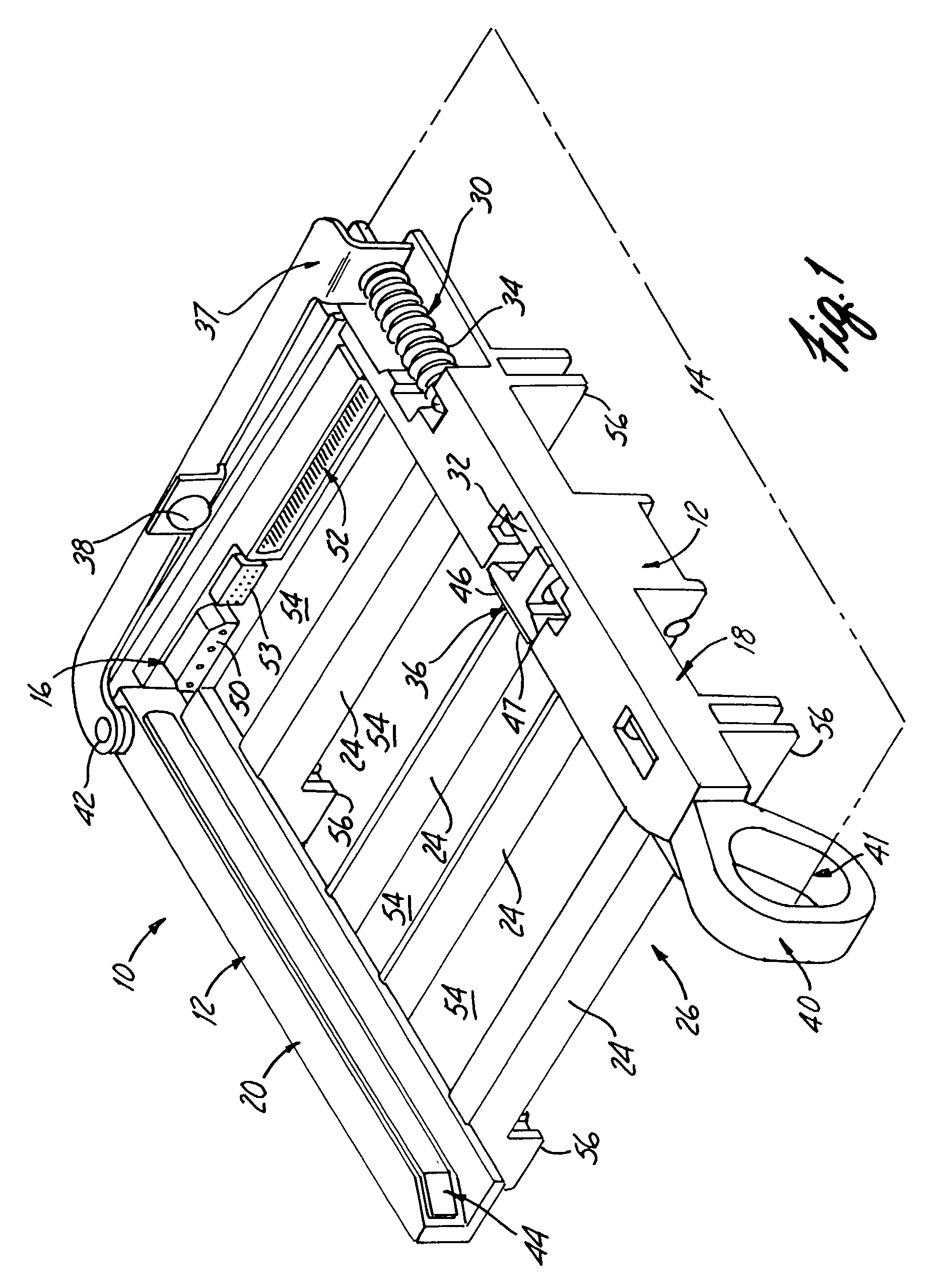
[0043]FIG. 1 is a perspective view of the top, right, and front sides of one carrier embodiment 10. The carrier 10 includes a frame 12, a clamping mechanism 14, and a connector bar 16. The frame 12 comprises an “L” shaped right side frame member (“right side bar”) 18, a left side frame member (“left side bar”) 20 that is generally parallel to and coplanar with the right side bar 18, and a plurality of generally transverse cross members (“cross bars”) 24 that cooperate with the right side bar 18 and the left side bar 20 to define a rectangular test bed 26. The clamping mechanism 14 in this embodiment comprises a cylindrical operating rod 30, a linear cam 32, a linear return spring 34, a clamp pad 36, an ejection lever 37, an ejection bumper 38, a non-interfering handle 40, and a hinge 42. The connector bar or module 16 comprises a variety of electrical connections, such as a power supply port 50, an I / O port 52, and a configureable jumper port 53.

[0044]In operation, the user may firs...

first embodiment

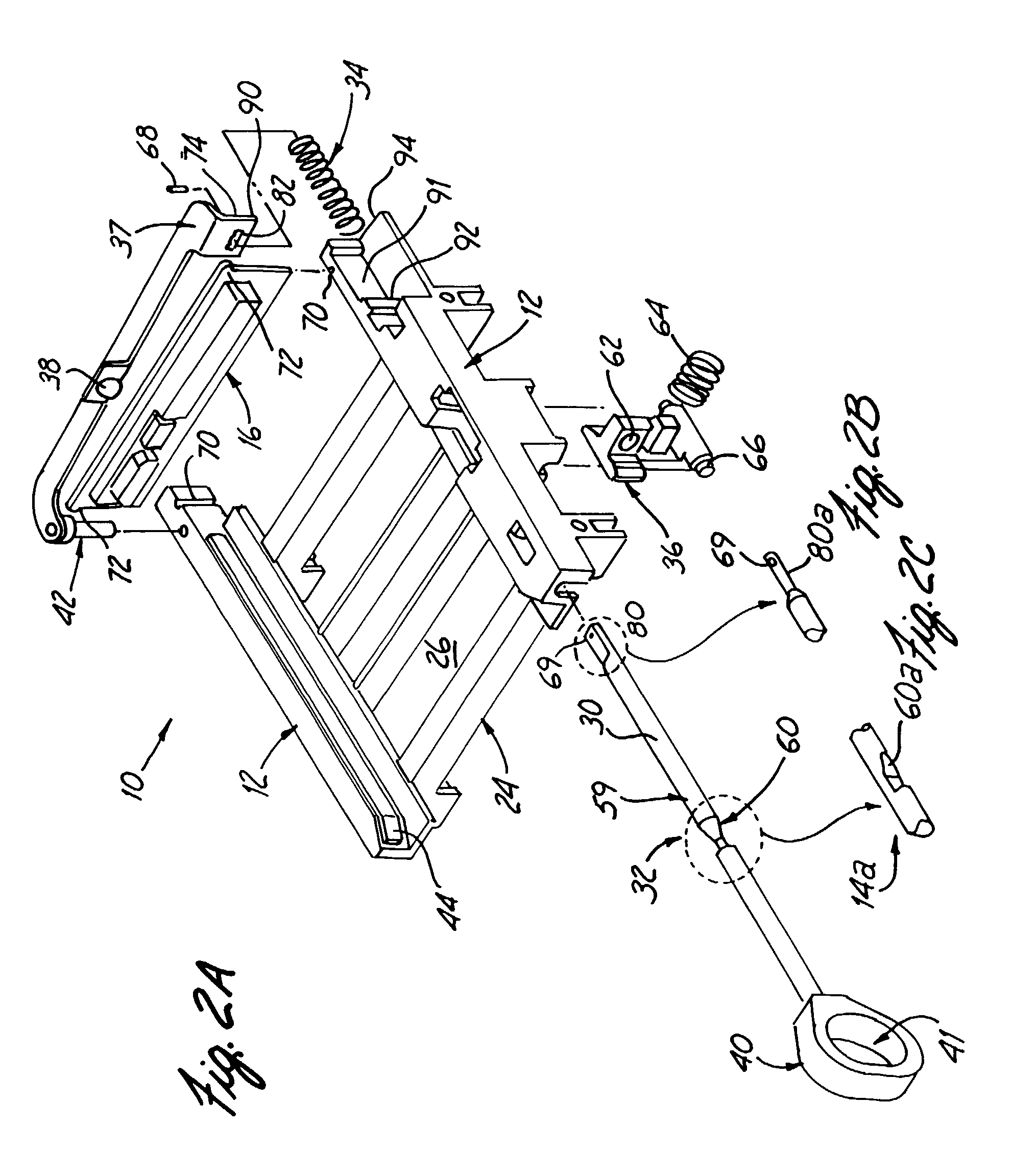
[0055]FIG. 2A is an expanded view showing the clamping mechanism 14. FIG. 2A comprises an operating rod 30 having large diameter section 59 and a grooved section 60 that combine to form the linear cam 32. The diameter of the large diameter section 59 is designed such that the operating rod 30 can slide freely through a hole 62 in the clamping pad 36. FIG. 2A also shows an actuating spring 64 and a hinge pin 66.

[0056]In operation, the grooved section 60 is aligned with the hole 62 when the operating rod 30 is in a fully inserted or “clamping” position. In this position, there is sufficient space between the operating rod 30 and the hole 62 such that the actuating spring 64 can pivot the clamping pad 36 around the hinge pin 66 and into engagement with the hard drive. That is, the actuating spring 64 can bias the clamping pad 36 against the hard drive when the grooved section 60 is laterally aligned with the hole 62. Sliding the operating rod 30 out of the “clamping position” laterally...

second embodiment

[0060]In a second embodiment clamping mechanism embodiment, the operating rod 30 may also be contoured along its length to form the linear cam 32. In this embodiment, the sections having a greater diameter may force the clamp pad 36 to move “inward” into the test bed and into contact with the hard disk drive. The portions of the operating rod having a smaller diameter may allow the clamp pad 36 to move “outward,” which releases the hard drive. The greater diameter sections in these embodiments are positioned along the length of the operating rod 30 such that the clamp pad 36 is forced to engage the drive when the handle 40 is in the “pushed in” or “clamping” position. The smaller diameter sections are positioned along the length of the operating rod 30 such that the clamp pad 36 can release the hard disk drive when the handle 40 is in the “home” and “ejection” positions.

[0061]The return spring 34 may also be used in the second embodiment to actuate the handle 40 from an “ejection” p...


PUM


Abstract

One aspect of the present invention is a system of fabricating a barrier wall between the testing and tester volumes of an environmental test chamber. This aspect may use a plurality of pallets adapted to receive a device under test and a testing apparatus, a framework adapted to receive a plurality of pallets, and a plurality of insulation bricks associated with the plurality of pallets. The insulation bricks may be adapted such that they can cooperate to form an insulating barrier between the device under test and the testing apparatus.

Description

CROSS-REFERENCE TO RELATED APPLICATION(S)[0001]This application is a divisional of Non-Provisional application Ser. No. 09 / 631,055, filed Aug. 1, 2000, and now U.S. Pat. No. 6,526,841, which claims benefit of Provisional Application No. 60 / 146,812, filed Aug. 2, 1999; Provisional Application No. 60 / 146,988, filed Aug. 3, 1999; Provisional Application No. 60 / 158,280, filed Oct. 7, 1999; and Provisional Application No. 60 / 170,939, filed Dec. 15, 1999.TECHNICAL FIELD[0002]This invention generally relates to environmental test chambers and apparatuses for use therein. More particularly, the present invention relates to a hard drive carrier, suitable for use in an environmental test chamber, having improved flexibility, mechanical stability, enhanced maintainability, and thermal uniformity. The present invention also relates to a barrier wall, and a method of construction thereof, for isolating a test area from a pseudo-ambient area in an environmental test chamber. In addition, the pres...

Claims


Application Information

Patent Timeline
IPC IPC(8): G01N17/00G01R31/28
CPCG01R31/2849
Inventor WANEK, DONALD L.SWANSON, LOREN L.SANDS, RICHARD L.TROUTMAN, MARKMELVILLE, JAMES A.
Owner BENCHMARK ELECTRONICS SUZHOU
Why Eureka
Try Eureka