Integrated cooler for electronic devices

Inactive Publication Date: 2006-07-04
ROTYS
View PDF21 Cites 46 Cited by
  • Summary
  • Abstract
  • Description
  • Claims
  • Application Information

AI Technical Summary

Benefits of technology

[0018]The objectives of the present invention are to realize an integrated combination heat sink-blower-electric drive having relatively

Problems solved by technology

Cooling is important because if left unchecked, heat can cause electronic components to malfunction during use or lead to premature component failure.
Additionally, improved processors require larger power supplies and auxiliary components that generate increased amounts of heat and require improved systems for heat removal.
The trend toward smaller and thinner electronic devices having larger, faster processors renders the traditional heat removal cooling systems inadequate for several reasons.
First, smaller devices having faster processors result in an increased density of heat producing electronic components leading to higher localized concentrations of heat.
Also, a decreased amount of space is available for localized temperature regulating devices such as traditional heat sinks.
Lastly, a decreased amount of space is available to create ventilation paths that pass by heat sources.
However, due to the weak airflow in the area adjacent to fan axle, the conditions for cooling the central part of the heat sink located underneath the hub are unfavorable.
In this case non-uniform cooling of the heat sink and electronic component will take place allowing for bad c

Method used


Image

  • Integrated cooler for electronic devices
  • Integrated cooler for electronic devices
  • Integrated cooler for electronic devices

Examples


first embodiment

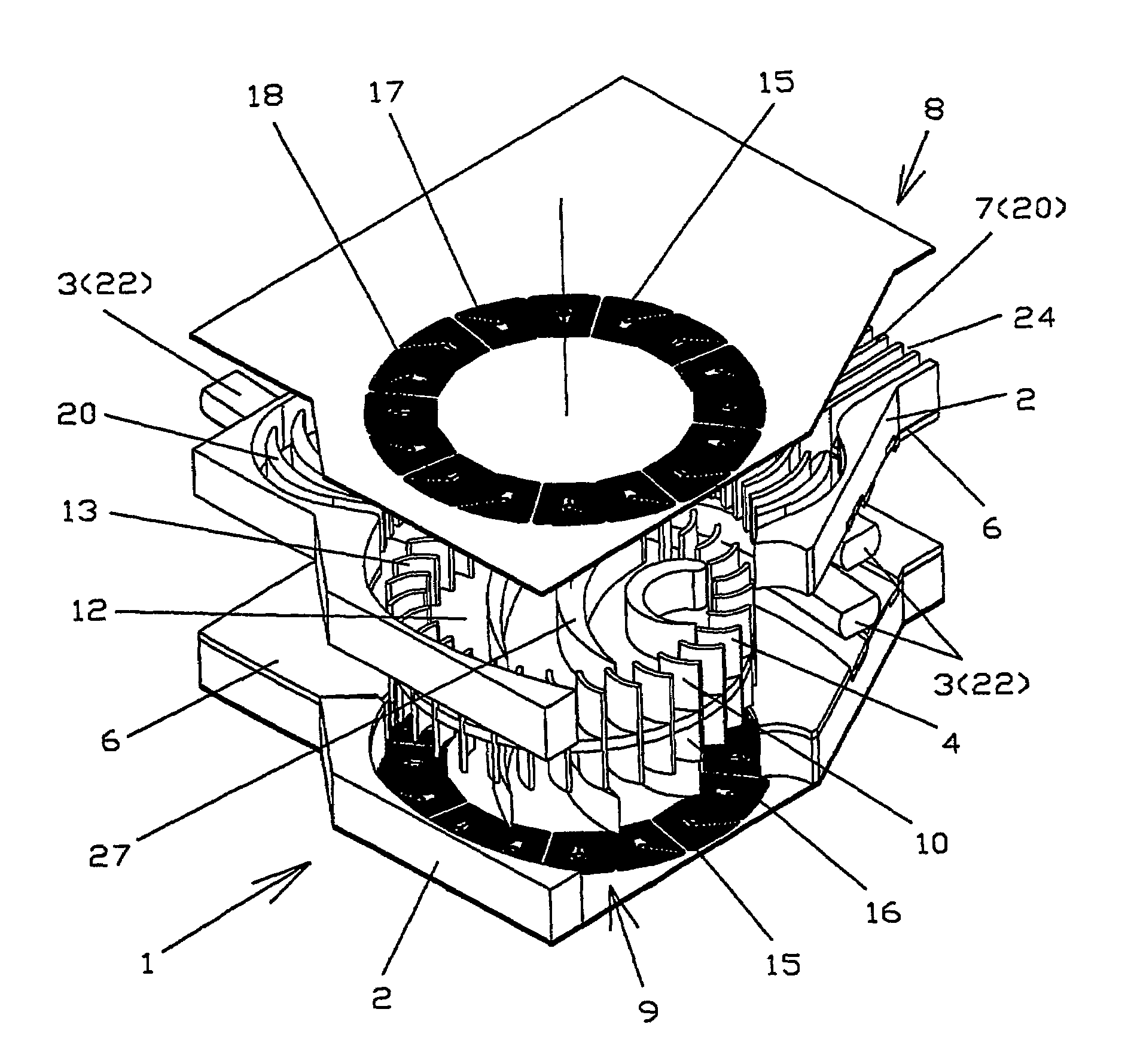
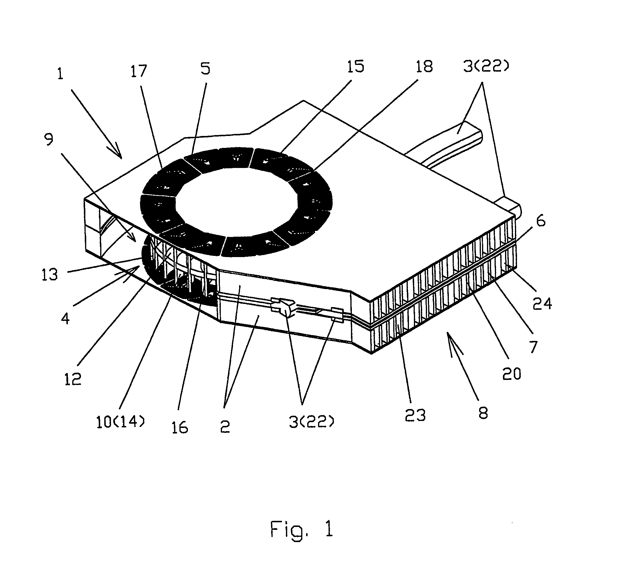
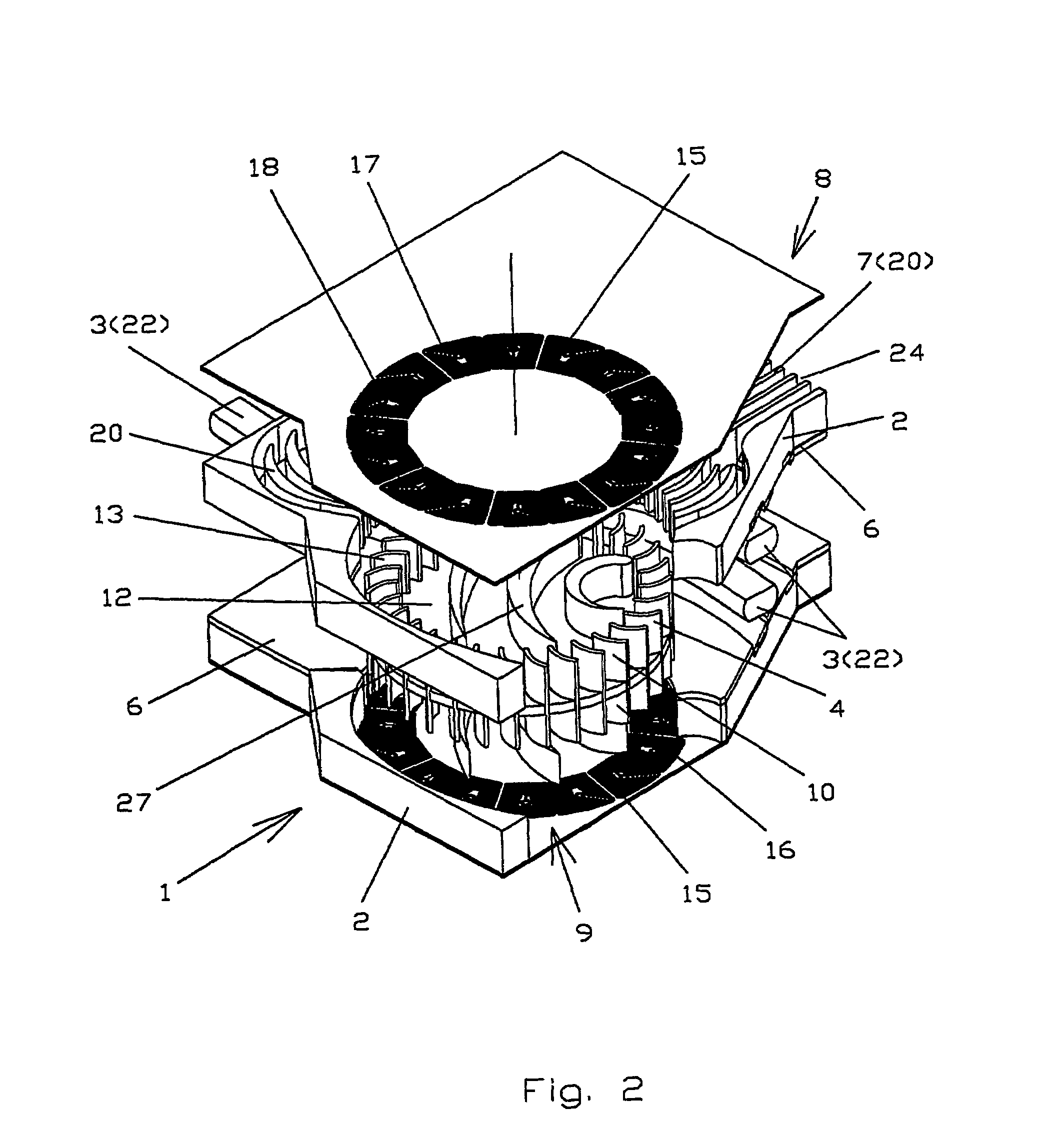
[0049]FIGS. 1–8 show the present invention.

[0050]The integrated cooler 1 for electronic devices comprises at least one heat exchange element 2, at least one heat transferring element 3, a blower 4 and an electric drive 5. The heat exchange element 2 includes a heat spreading base 6 and heat exchanging means 7 made on a surface of the base 6. The heat spreading base 6 provides thermal contact with the heat transferring elements 3. FIGS. 1–4 and 8 illustrate two heat transferring elements 3. The heat transferring element 3 may be an electronic device 21 (see FIG. 8), a heat-pipe 22 or another heat transferring element 3 made from a high heat-conducting material. The heat exchanging means 7 are pins 19 and / or fins 20.

[0051]The blower 4 comprises a blower inlet 8 and a blower outlet 9, which are directly connected to ambient air, so that the integrated cooler for electronic devices 1 becomes a hydraulically sealed unit. It is possible to use any other cooling gas, not only ambient air. ...

second embodiment

[0073]FIGS. 10 and 11 show the present invention.

[0074]The second embodiment differs from the first embodiment only in that the blower inlet 8 and blower outlet 9 have a different design.

[0075]Other components are the same as in the first embodiment. Therefore the components the same as in the first embodiment are denoted with the same reference numerals, for which description is partly omitted.

[0076]The integrated cooler 1 for electronic devices comprises at least one heat exchange element 2, at least one heat transferring element 3, a blower and an electric drive 5 (not shown for simplicity). The heat exchange element 2 includes a heat spreading base 6 and heat exchanging means 7 made on a surface of the base 6. The heat spreading base 6 provides thermal contact with the heat transferring elements 3. The heat transferring element 3 is a heat-pipe 22. The heat exchanging means 7 are fins 20 that covered from upper side with covering plates (not shown in FIGS. 10 and 11).

[0077]The b...


PUM


Abstract

An integrated cooler for electronic devices comprises a heat exchange element, a heat transferring element and a blower with an electric drive. The heat exchange element comprises a base and heat exchanging means. The electronic device directly thermally connected with the base or the heat exchanging means by the heat transferring element. The blower comprises an inlet, an outlet and a drum type impeller comprises a disk with blades mounted on an axle fixed perpendicularly to the base. The heat exchanging means located at the inlet and/or at the outlet, thus ambient air flows through the inlet, the impeller and the outlet in a series way and in the directions perpendicular to the axle, so that the blower is a crossflow type blower. The electric drive comprises a rotor and a stator. The rotor made as the impeller having circumferential arrayed magnetic means. The stator comprises circumferential arrayed coils.

Description

[0001]This application is a U.S. National Phase Application under 35 USC 371 of International Application PCT / US02 / 28409 filed Sep. 6, 2002 which claims the benefit of priority of U.S. Provisional Patent Application Ser. No. 60 / 318,246, filed Sep. 7, 2001, the entire contents of which are hereby incorporated by reference.FIELD OF THE INVENTION[0002]The present invention relates generally to cooling systems. More particularly, the present invention relates to cooling systems for regulating the temperature of electronic devices. The present invention is particularly, but not exclusively, useful for a cooling system for regulating the temperature of electronic components of a laptop computer.BACKGROUND OF THE INVENTION[0003]The regulation of the temperature due to heat generated inside the housing of an electronic device is an important consideration during the design of an electronic device. Cooling is important because if left unchecked, heat can cause electronic components to malfun...

Claims


Application Information

Patent Timeline
IPC IPC(8): H02K9/00F04B17/00H02K1/22H02K9/06G06F1/20H01L23/467H05K7/20
CPCF04D17/04G06F1/203H01L23/467Y10S310/06H01L2924/0002H01L2924/00F04D25/0606F04D25/0653
Inventor LOPATINSKY, EDWARD L.SHAEFER, DAN K.ROSENFELD, SAVELIY T.FEDOSEYEV, LEV A.
Owner ROTYS
Why Eureka
Try Eureka