
Stick-type ignition coil having improved structure against crack or dielectric discharge

Inactive Publication Date: 2006-07-04
DENSO CORP
View PDF87 Cites 5 Cited by
  • Summary
  • Abstract
  • Description
  • Claims
  • Application Information

AI Technical Summary

Benefits of technology

[0012]It is an object of the present invention to provide an ignition coil capable of suppressing drawbacks caused by a changes in surrounding temperature.
[0013]It is another object of the invention to provide an ignition coil capable of suppressing cracks from occurring in the vicinity of the longitudinal end corners of the a central core and / or outer core.
[0014]It is a further object of the invention to provide an ignition coil capable of suppressing dielectric breakdown caused by changes in surrounding temperature.

Problems solved by technology

Then, the resin insulator or the case member, as contacting with the central core, especially the resin insulator or the case member contacting the longitudinal end corners of the central core, may crack, which results in defective electric insulation.
Especially when the central core receives the load in the longitudinal direction, the magnetic permeability of the core may drop causing magneto-striction which disables generation of a required high voltage.
As a result, the insulator contacting with the outer core may crack causing an electric discharge between the secondary coil or a high voltage terminal the outer core.
This over coating is not applicable to the stick-type ignition coil, however, because the stick-type is so regulated in its external diameter as to match the internal diameter of the plug hole.

Method used


Image

  • Stick-type ignition coil having improved structure against crack or dielectric discharge
  • Stick-type ignition coil having improved structure against crack or dielectric discharge
  • Stick-type ignition coil having improved structure against crack or dielectric discharge

Examples


first embodiment

[0060](First Embodiment)

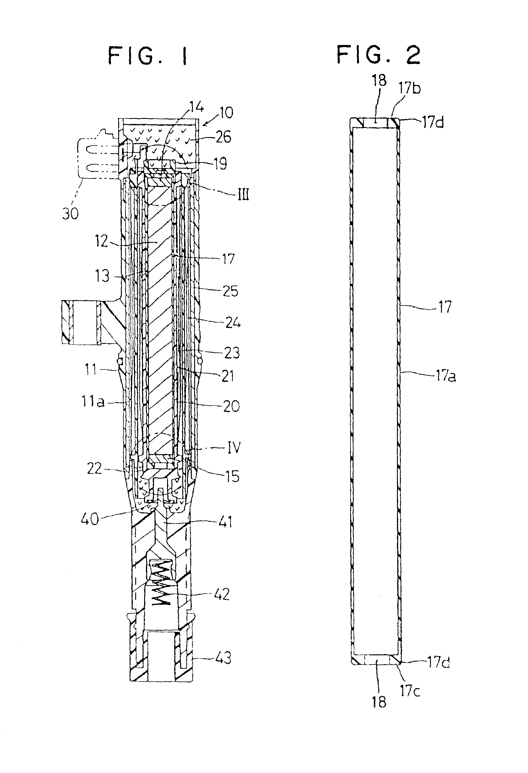
[0061]An ignition coil 10 is fitted, as shown in FIG. 1, in a plug hole (not shown) which is formed in each cylinder head of an internal combustion engine, and is electrically connectable to a spark ignition plug.

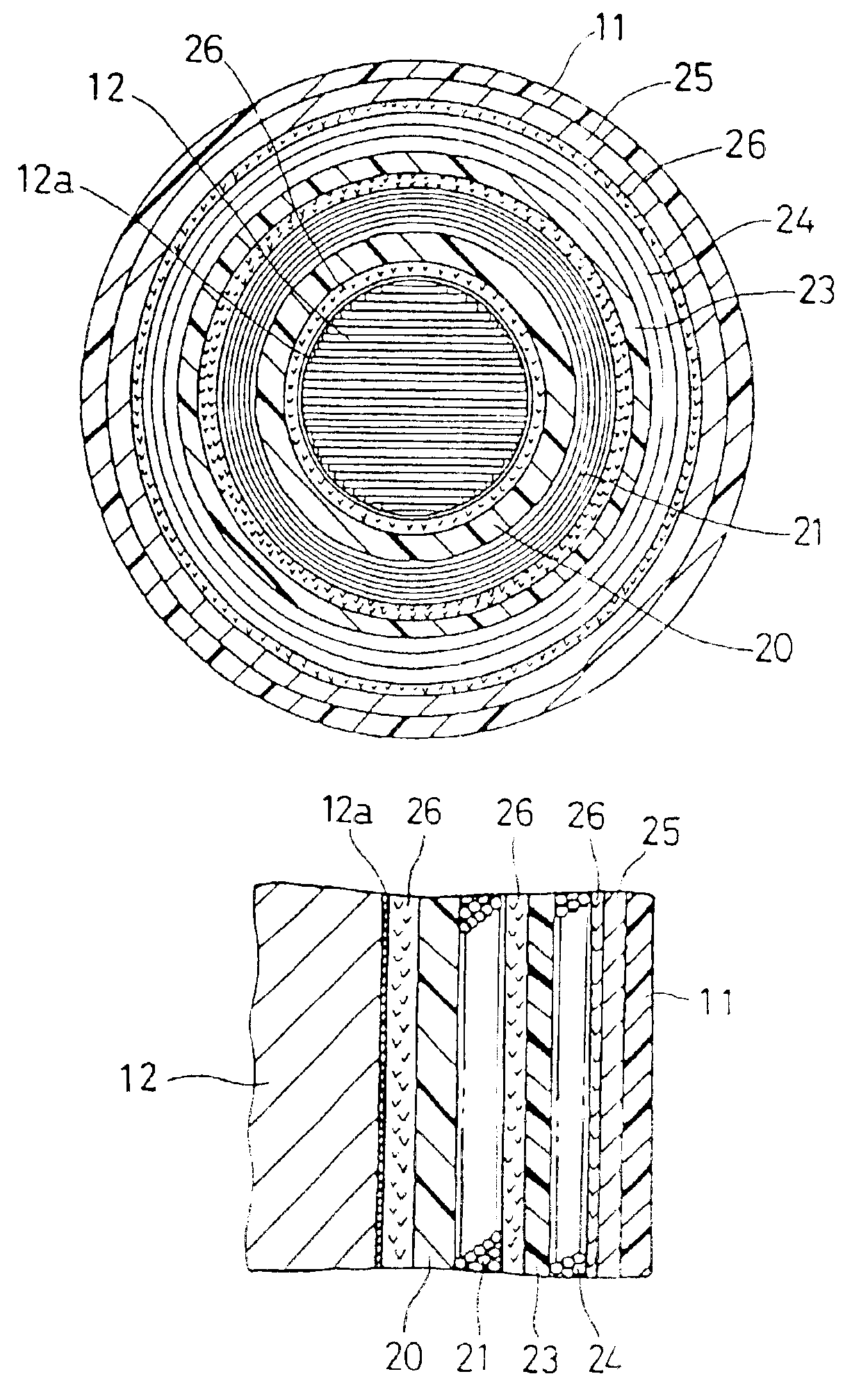
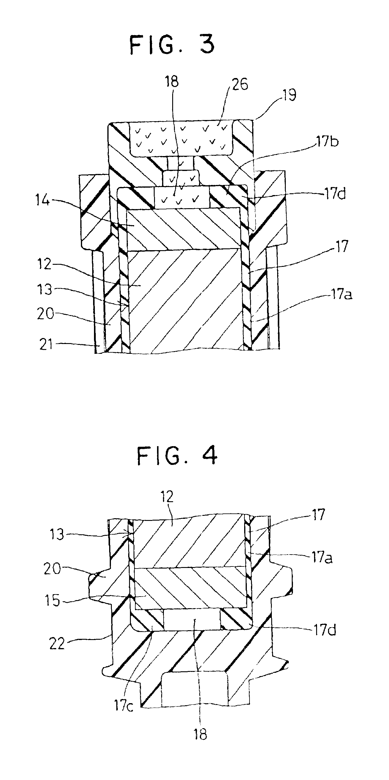
[0062]The ignition coil 10 has a cylindrical housing 11 made of a resin, in which an accommodating chamber 11a is formed to accommodate a central core assembly 13, a secondary spool 20, a secondary coil 21, a primary spool 23, a primary coil 24 and an outer core 25. The central core assembly 13 is comprised of a core 12, and permanent magnets 14 and 15 arranged at the two longitudinal ends (top and bottom) of the core 12. An epoxy resin26 filled in the accommodating chamber 11a infiltrates between the individual members of the ignition coil 10 to ensure the electric insulations among the members as a resin insulating material.

[0063]The core 12 having a column shape is provided by laminating a thin silicon (Si) steel sheet radially to have a generally...

second embodiment

[0073](Second Embodiment)

[0074]In the second embodiment shown in FIG. 5, no the permanent magnets are arranged at the two longitudinal ends of the core 12, but the core 12 itself provides the central core assembly 13. The core 12 is covered partially at the outer circumference, at the two end corners and at the two longitudinal end faces with the cylindrical member 17.

[0075]In the second embodiment, too, the cracks can be prevented around the outer circumference of the core 12 and especially at the secondary spool 20 and the epoxy resin 26 in the vicinity of the two end corners of the core 12, where the cracks might otherwise be liable to occur, so that the electric discharge between the high voltage side and the central core assembly 13 can be prevented. As a result, the desired high voltage can be applied to the ignition plug.

[0076]As a result of the elastic deformation of the cylindrical member 17, moreover, the forces for the core 12 to receive in the radial direction and in the...

third embodiment

[0077](Third Embodiment)

[0078]In the third embodiment shown in FIGS. 6 and 7, the cylindrical member 17 made of rubber to act as the first buffer member is comprised of the cylindrical part 17a, an angled part 17b and a bottom disc part 17c acting as a second buffer member, and is shaped into a bottomed cylindrical shape, as closed at the bottom longitudinal end side of the permanent magnet 15. The cylindrical part 17a covers the outer circumference of the central core assembly 13, the annular angled part 17b covers the end corner of the permanent magnet 15, and the disc part 17c covers the bottom end face of the permanent magnet 15. The cylindrical member 17 is extended upwardly at the side of the permanent magnet 14 over the end face of the permanent magnet 14. A plate member 17e made of rubber to act as the first buffer member and the second buffer member is formed into a disc shape separate from the cylindrical member 17 and has a larger diameter than the permanent magnet 14. Th...


PUM


Abstract

A stick-type ignition coil have a central core, a cylindrical member, primary spool, primary coil, secondary spool, secondary coil, outer core and a resin insulator. The two longitudinal end corners and faces of the core are covered by respective buffer members. The inner circumferential corners of the outer core is supported by ring members. Some of the members disposed radially inside and other members disposed radially outside of the inside members are held slidably to each other in the ignition coil. The spools are made of resin containing a rubber in excess of 5 weight percent and reinforcing materials. The resin insulator contains a flexible material.

Description

[0001]This application is a division of application Ser. No. 09 / 635,137, filed Aug. 9, 2000 now U.S. Pat. No. 6,525,636, which was a division of application Ser. No. 09 / 023,613, filed Feb. 13, 1998 U.S. Pat. No. 6,208,231, the entire contents of each of which is hereby incorporated by reference in this application.CROSS REFERENCE TO RELATED APPLICATION[0002]This application relates to and incorporates herein by reference Japanese Patent Application Nos. 9-30403, 9-30404, 9-110836, 9-173947, 9-213626, 9-214939, 9-214940, 9-214941, 9-214943, 9-357011 and 9-357143, filed on Feb. 14, 1997, Feb. 14, 1997, Apr. 28, 1997, Jun. 30, 1997, Aug. 7, 1997, Aug. 8, 1997, Aug. 8, 1997, Aug. 8, 1997, Aug. 8, 1997, Dec. 25, 1997 and Dec. 25, 1997, respectively.BACKGROUND OF THE INVENTION[0003]1. Field of the Invention[0004]The present invention relates to an ignition coil for an internal combustion engine and, more particularly, to a stick-type ignition coil to be fitted directly in the plug hole of...

Claims


Application Information

Patent Timeline
IPC IPC(8): H01F27/30H01F27/02H01F27/32H01F38/12
CPCH01F27/327H01F38/12H01F27/022H01F2038/125H01F2038/122
Inventor KAWANO, KEISUKEWAKABAYASHI, HIROYUKISUGIURA, AKIMITSU
Owner DENSO CORP
Learn More