Data read device, read method and circuit controlling read device

a data read device and read method technology, applied in special recording techniques, maintaining head carrier alignment, instruments, etc., can solve problems such as possible read errors, and achieve the effect of shortening the time needed to adap

Inactive Publication Date: 2006-07-04
TOSHIBA STORAGE DEVICE CORP
View PDF3 Cites 71 Cited by
  • Summary
  • Abstract
  • Description
  • Claims
  • Application Information

AI Technical Summary

Benefits of technology

[0028]It is a first object of the present invention to shorten the time needed to adapt each circuit that constitutes a read channel to the change in en...

Problems solved by technology

If the function of the read unit degrades due to the change of environmental temperature or the degradation of a read head, there is a high po...

Method used


Image

  • Data read device, read method and circuit controlling read device
  • Data read device, read method and circuit controlling read device
  • Data read device, read method and circuit controlling read device

Examples


Embodiment Construction

[0053]The preferred embodiments of the present invention are described below with reference to the drawings. The same device and the like are denoted by the same reference numerals throughout the description and their descriptions are omitted. Although a magnetic disk is used as an example for convenience's sake, a storage device to which the present invention is applicable is not limited to this, as described later.

[0054]FIG. 4 shows the configuration of a magnetic disk device according to the present invention. In FIG. 4, thin and bold arrow marks indicate the flow of a control signal and that of data, respectively. As shown in FIG. 4, the magnetic disk device largely comprises a disk enclosure unit and a circuit substrate. The disk enclosure unit further comprises a magnetic disk medium 1 and a pre-amplifier 2. The circuit substrate further comprises an RDC 100, an MCU (micro controller unit) / DSP (digital signal processor) / peripheral logic 3, an HDC (hard disk controller) 4 and a...


PUM


Abstract

An HDC asserts the read gate of an RDC when a read head is positioned in a sector located before a sector that a hot system instructs to read data when seen from the rotation direction of a storage medium. The data that the read head has read from the sector is used to adapt a circuit that constitutes the RDC. However, the data is not transferred to the host system. Such a process is repeated until the read head reaches a position where data stored in a sector whose data has been instructed to read can be read. In this way, time needed to adapt a circuit that constitutes a read channel can be shortened.

Description

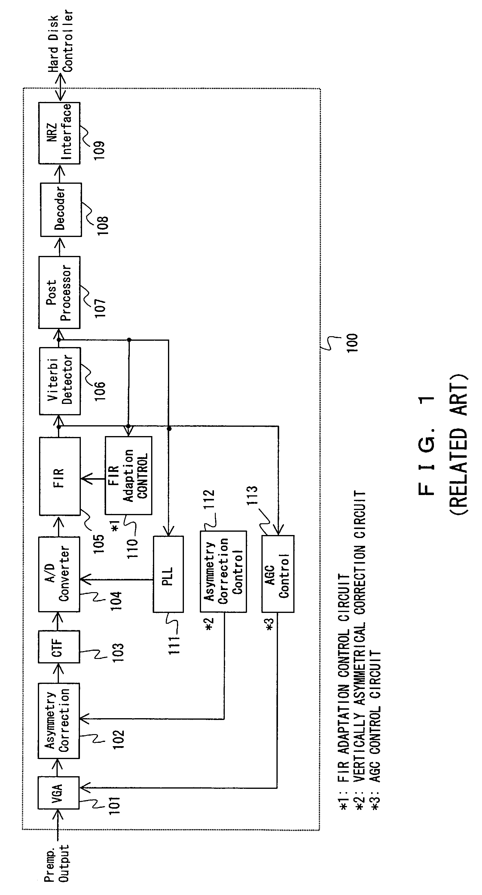
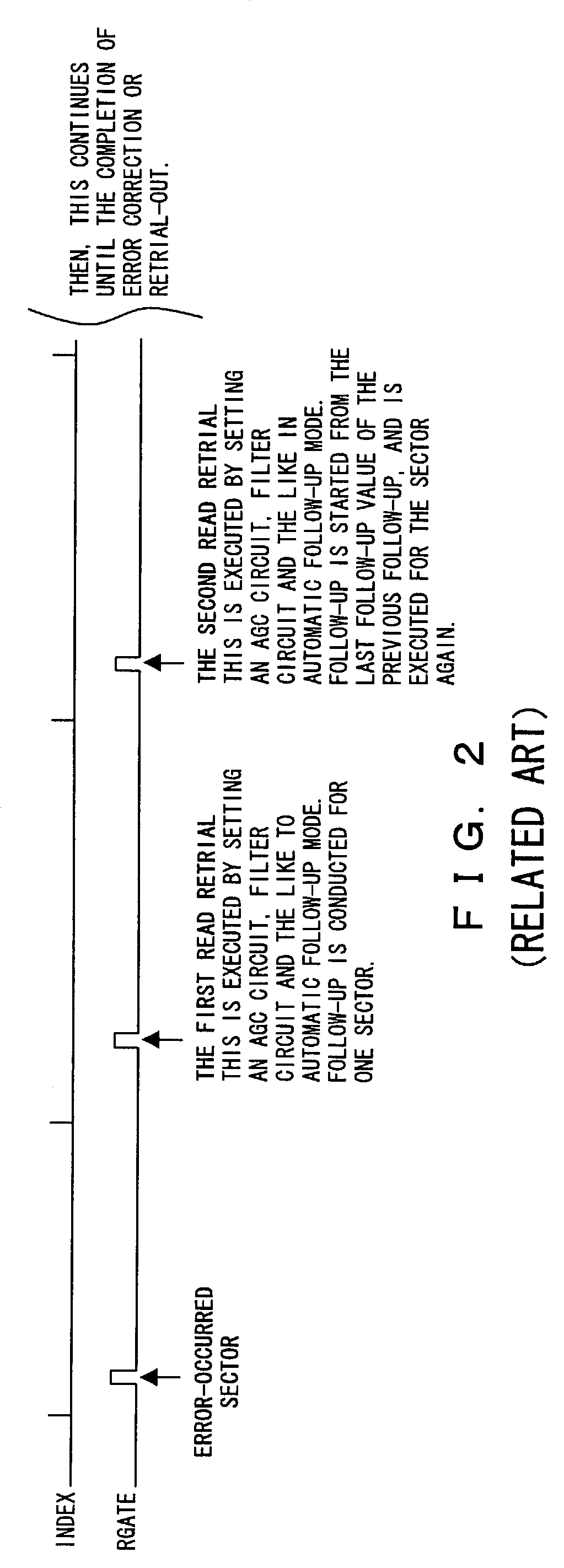
BACKGROUND OF THE INVENTION[0001]1. Field of the Invention[0002]The present invention relates to a control method for controlling storage devices in such a way as to maximize their read performance according to a variety of environmental changes, and a retrial method used when data reading from a storage medium fails.[0003]2. Description of the Related Art[0004]With high-density storage of a magnetic disk device, the signal-to-noise ratio (S / N ratio) at the time of data reading has recently degraded. On the other hand, in order to correctly decode a read signal by a read head, an optimal modulation / demodulation method is adopted. Furthermore, the tuning of the parameters of a variety of read circuits, such as a pre-amplifier, the VGA (variable voltage amplifier) circuit of a read channel IC (hereinafter simply called a “read channel”), a filter control circuit and the like, is indispensable depending on the dispersion in characteristics of each read head and a magnetic disk medium.[...

Claims


Application Information

Patent Timeline
IPC IPC(8): G11B5/596G11B5/09G06F3/06G11B5/00G11B5/012G11B5/455G11B20/10
CPCG11B5/012G11B20/10009G06F3/0601G06F2003/0692G11B2005/0013G11B2005/001G11B5/455G06F3/0673
Inventor CHIBA, HIROYUKI
Owner TOSHIBA STORAGE DEVICE CORP
Why Eureka
Try Eureka