
Temperature sensor

a technology of temperature sensor and polarizer, which is applied in the direction of positive temperature coefficient thermistors, instruments, heat measurement, etc., can solve the problems of inability to position stably with respect to the tip section, and difficulty in making accurate temperature detection

Inactive Publication Date: 2006-07-11
MURATA MFG CO LTD
View PDF45 Cites 13 Cited by
  • Summary
  • Abstract
  • Description
  • Claims
  • Application Information

AI Technical Summary

Benefits of technology

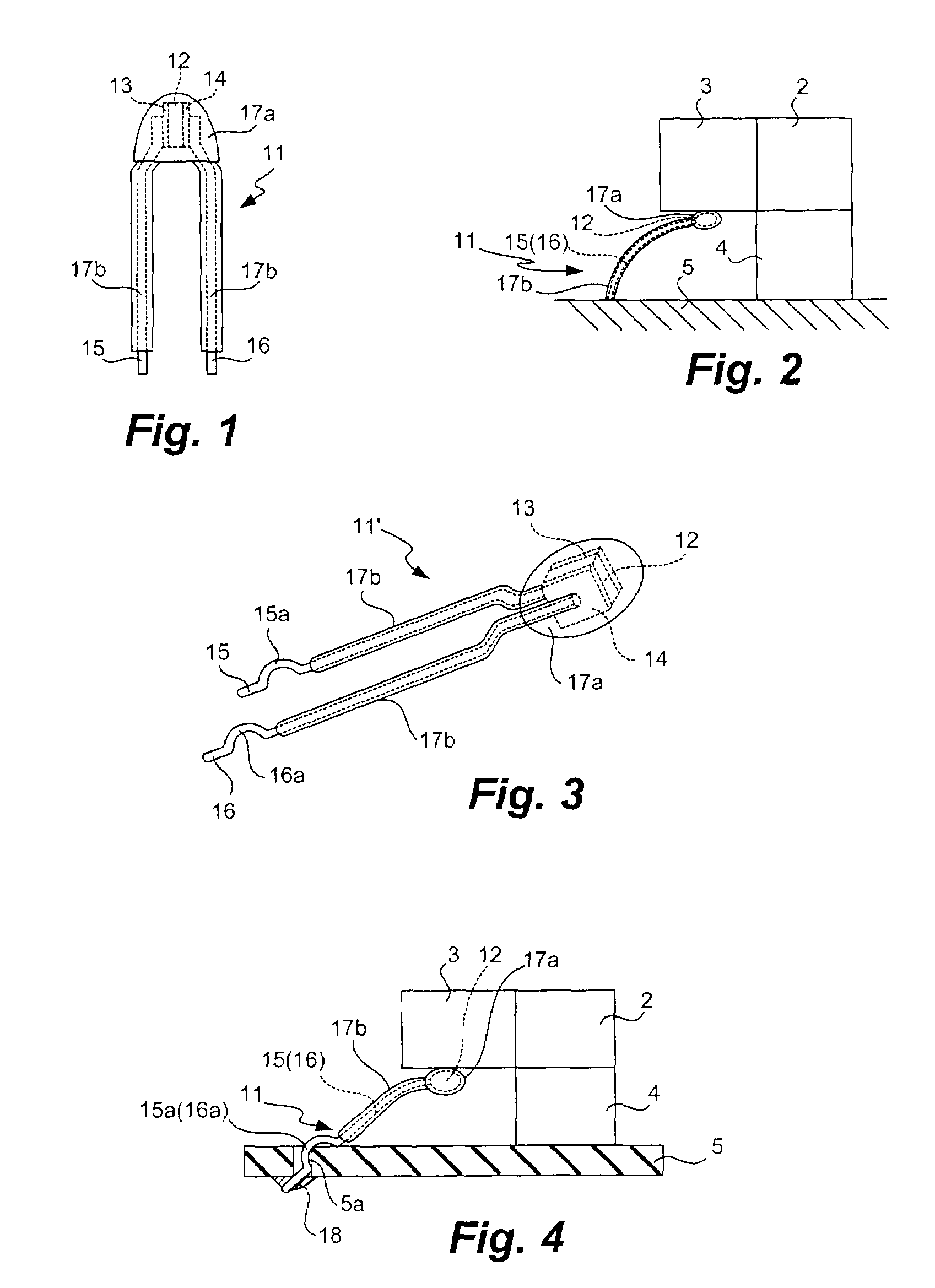
The invention provides an improved temperature sensor with elastic lead lines that can make reliable contact with the temperature sensing element and the target object for measurement. The lead lines bend in a desired direction, ensuring better contact. The sensor may have a temperature sensing element and elongated electrically conductive lead lines attached to the element, with non-straight parts that hook at throughholes in a base board. The lead terminals are securely and dependably connected to the temperature sensing element.

Problems solved by technology

Vibrations of the DC fan 3, furthermore, make it difficult to maintain a constant positional relationship between the temperature sensing element 108 and the DC fan 3, causing difficulties in making an accurate temperature detection.
Even after temperature sensing elements 152 are inserted, another problem is that they cannot always be positioned stably with respect to the tip sections 151c of the planar lead parts 151b in terms of the orientation (as shown in FIG. 12A) or the position (as shown in FIG. 12B).

Method used


Image

  • Temperature sensor
  • Temperature sensor
  • Temperature sensor

Examples


first embodiment

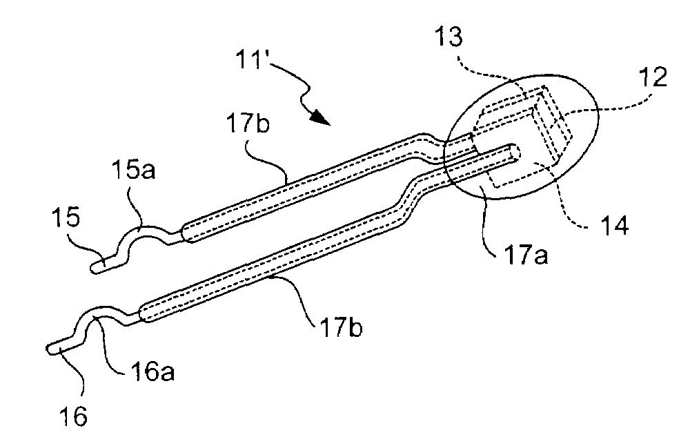
[0028]If the lead lines 15 and 16 are simply inserted into throughholes (not shown) through the printed circuit board 105 in a direction more or less perpendicular to its surface and the CPU 2 with the DC fan 3 is lowered from above after the temperature sensor 11 is fastened to the circuit board 5 (say, by soldering), the lead lines 15 and 16 may fail to bend in the desired direction or be crushed by the vertical downward force. According to a preferred variation to the invention, as shown generally at 11′ in FIG. 3, kinked parts 15a and 16a are provided respectively to the lead lines 15 and 16 where the lead lines 15a and 16a are bent in the same direction in a nearly semi-circular arcuate form, each of the kinked parts 15a and 16a being sandwiched between two mutually colinearly extending portions. The second outer cover 17b according to this embodiment is made somewhat shorter so as not to cover the kinked parts 15a and 16a for the convenience in the operations for mounting the ...

second embodiment

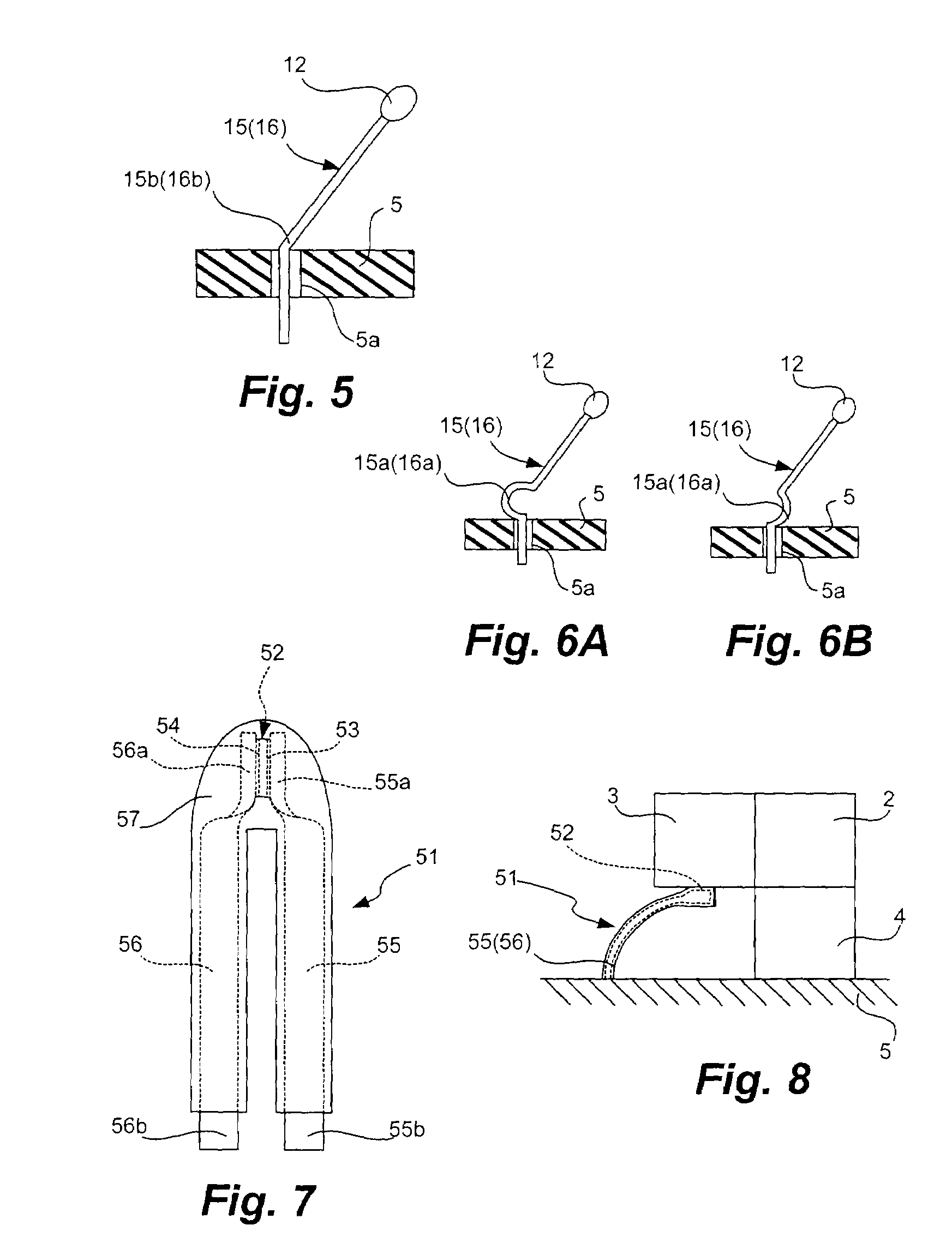
[0034]FIG. 7 shows a temperature sensor 51 according to this invention, comprising an NTC thermistor element 52 having a pair of terminal electrodes 53 and 54 formed on its mutually oppositely facing main surfaces, lead terminals 55 and 56 each with its top end parts 55a or 56a attached to a corresponding one of these terminal electrodes 53 and 54 (say, by a solder material (not shown)) and an outer cover 57 of an electrically insulating resin material covering the thermistor element 52 and the lead terminals 55 and 56 except their bottom end parts 55b and 56b. The NTC thermistor element 52 may not necessarily be in the shape of a chip but may be planar, for example, of a circular disk shape.

[0035]The lead terminals 55 and 56 may comprise phosphor bronze with hardness ½H and are planar, having a rectangular cross-sectional shape. The material for the lead terminals 55 and 56 may also be german silver, beryllium, SUS, a Cu—Ti alloy, brass or any of these with plating. The lead termin...


PUM

PropertyMeasurementUnit
thicknessaaaaaaaaaa
angleaaaaaaaaaa
angleaaaaaaaaaa

Abstract

A temperature sensor has lead lines made of an elastic material each attached to a corresponding one of electrodes on a temperature sensing element such as an NTC thermistor element. The lead lines may each have a non-straight part where they are bent or deformed into a semi-circular shape such that, when these lead lines are inserted into throughholes prepared through a circuit board, the non-straight parts are hooked at the throughholes and the portions of the lead lines above the circuit board will stand up obliquely. Instead of lead lines, a pair of elongated planar lead terminals each with a twisted top end part may be connected to the electrodes such that the top end parts of the pair of lead terminals face each other and can support the temperature sensing element more securely in between.

Description

BACKGROUND OF THE INVENTION[0001]This invention relates to a temperature sensor provided with lead lines or planar lead terminals and, more particularly, to such a temperature sensor comprising a thermistor.[0002]A thermistor element with a negative temperature coefficient (or an NTC thermistor element) is usually used as the temperature sensing element for such a temperature sensor and is sometimes directly contacted to a target object, such as a CPU carried on a mother board, in order to accurately measure its temperature. FIGS. 10A and 10B show an example of prior art temperature sensor 101 of this type for detecting the heat generated by a CPU 2 connected to a printed circuit board 105 through a socket 4, the temperature sensor 101 being contacted to a DC fan 3 for cooling the CPU 2. The prior art temperature sensor 101 is characterized as having lead lines 106 and 107 which are made, for example, of a plated wire such as a hard copper or steel wire covered with copper or strand...

Claims


Application Information

Patent Timeline
Patent Type & Authority Patents(United States)
IPC IPC(8): H01C7/10G01K1/08G01K1/14H01C1/14
CPCH01C1/1413G01K1/14G01K1/08
Inventor KAWAMOTO, TETSUYAYAMADA, HIDEKIKOBAYASHI, HIROYUKISHIMADA, MINORUOHMURA, KINGOWAKABAYASHI, ASAMI
Owner MURATA MFG CO LTD
Learn More