
Optical pickup

a pickup and optical technology, applied in the field of optical pickups, can solve the problems of poor quality light convergence to the focused spot, difficult to ensure compatibility, and rapid increase in coma aberration, and achieve the effect of aversatile optical pickup

Inactive Publication Date: 2006-07-11
SHARP KK
View PDF4 Cites 7 Cited by
  • Summary
  • Abstract
  • Description
  • Claims
  • Application Information

AI Technical Summary

Benefits of technology

[0011]The present invention has an objective to provide a versatile optical pickup capable of recording / reproducing information on two types of recording media in a satisfactory manner irrespective of the reproduction wavelengths or substrate thicknesses of the recording media.
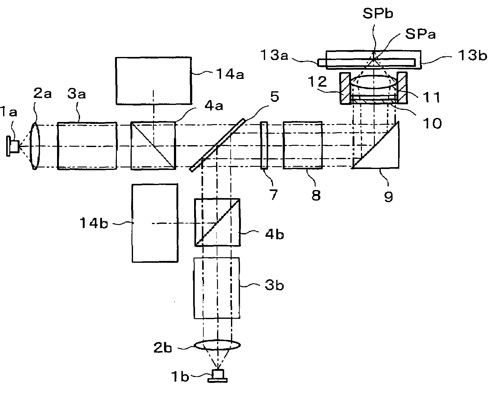
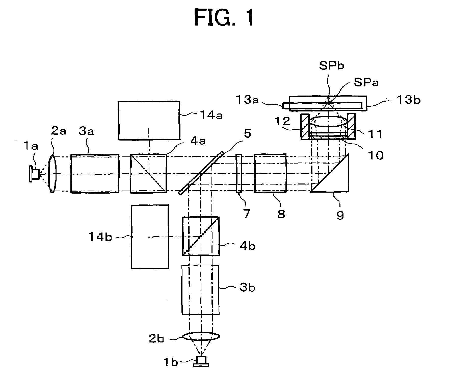
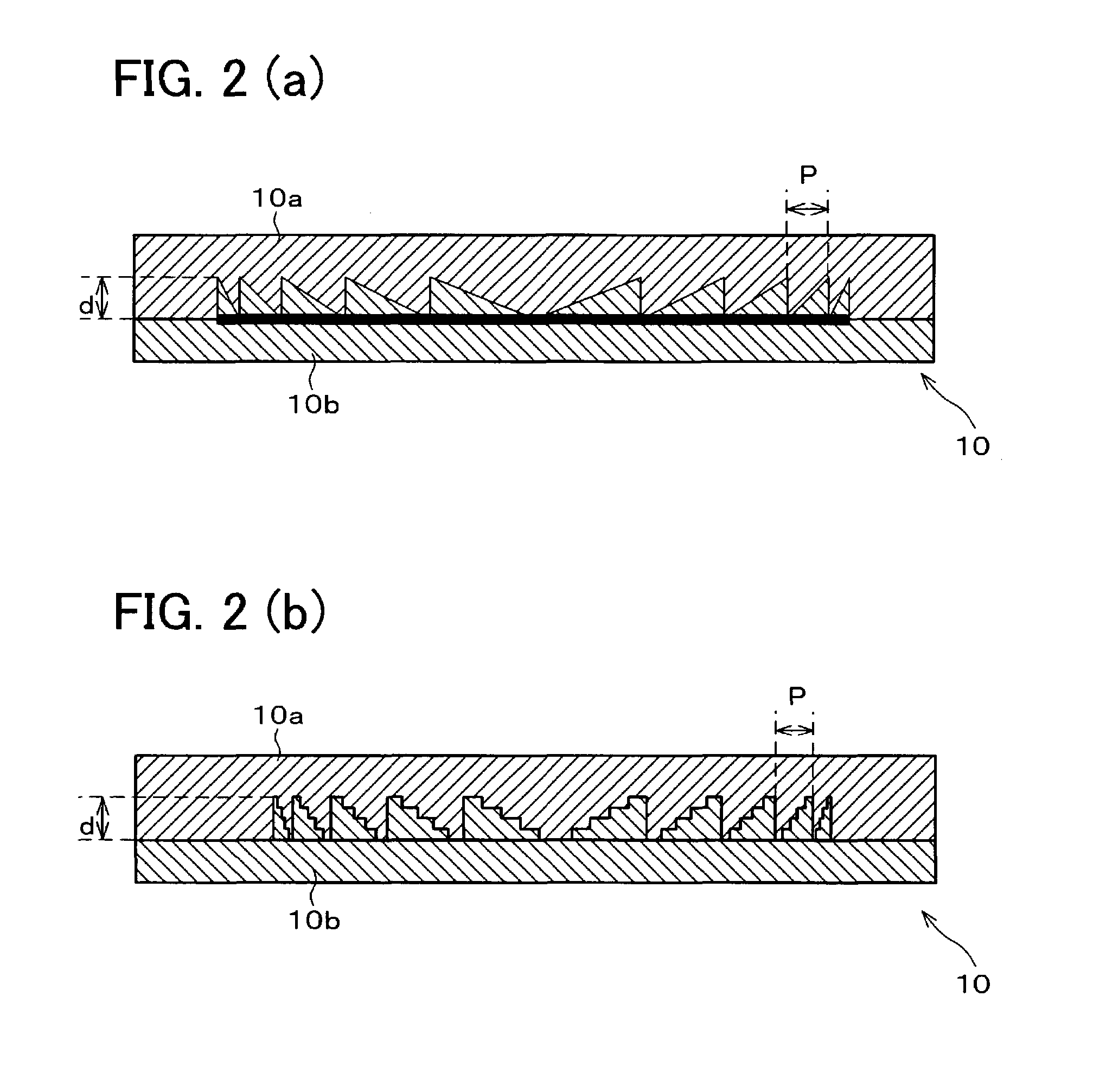
[0021]Since the combination-type diffractive element is fabricated from raw materials selected so that the materials have nearly equal refractive indices at one of the wavelengths, the configuration improves utilization efficiency of the light at the wavelength. The light at the other wavelength achieves good recording / reproduction with a recording medium, because the grating is shaped so as to form a light-collecting spot on the information recording plane of the recording medium. The structure enables a good light-collecting spot to be formed both on the first and second recording media for which light is used in recording / reproduction at two wavelengths which differ vastly from each other, irrespective of the wavelengths or substrate thicknesses of the recording media.

Problems solved by technology

Increasing the NA of an objective lens leads to quick increases in coma aberration, a phenomenon which occurs when the optical disk is tilted.
This in turn raises an issue of poor quality light convergence to the focused spot.
However, as described above, the next generation high density optical disk differs from the DVD in thickness of the optical disk substrate, making it difficult to ensure compatibility.
An ordinary objective lens is designed assuming a substrate thickness of a particular optical disk; if the lens is used with an optical disk having a vastly different substrate thickness from the designed value, a spherical aberration, hence poor light convergence occurs at the focused spot.
However, it entails the following problems to apply the conventional techniques to make the next generation high density optical disk compatible with the DVD.
However, when applied to the compatibility issue between the next generation high density optical disk and the DVD where the two wavelengths has a large difference and the objective lens has a high numerical aperture, the technique fails to correct aberrations which occurs to divergent incident light and poorly converges a diverging flux of incident light to the focused spot.
The correction lens cannot therefore be driven integrally with the objective lens, making it difficult to maintain performance when the objective lens is moved.
The technique therefore requires a laser source with a high output power, which raises a problem of high power consumption.
Such a low efficiency technique is not suited to an application in an optical pickup, also in view of the need for high output power in recording / erasing information on an optical disk.

Method used


Image

  • Optical pickup
  • Optical pickup
  • Optical pickup

Examples


example

[0072]The following will describe examples in accordance with the present invention.

[0073]In the present example, wavefront aberration was specifically calculated for the next generation high density optical disk (wavelength=405 nm, substrate thickness=0.1 mm) and the DVD (wavelength 650=nm, substrate thickness=0.6 mm). Results are shown below. The wavefront aberration calculation was based on a combination-type diffractive element 10 using two types of glass, TPH55 and SYGH52, and objective lenses configured as in Tables 2, 3. Table 2 shows a lens configuration for the next generation high density optical disk, whereas Table 3 shows the lens arrangement for the DVD.

[0074]

TABLE 2Next Generation High Density Optical DiskSurfaceCurvatureSurfaceNo.RadiusDistanceMaterialCombination-Type1Infinity0.20*1Diffractive2Infinity0.20*2Element3Infinity0.05Objective Lens5 1.412.40*3616.370.10Optical Disk7Infinity0.10Polycarbonate8Infinity0.252482*1: TPH55_OHARA*2: SYGH52_OHARA*3: LAH67_OHARA

[0075]...


PUM

PropertyMeasurementUnit
refractive indicesaaaaaaaaaa
wavelength λ2aaaaaaaaaa

Abstract

An optical pickup includes a semiconductor laser for emitting light at a wavelength λ1 and a semiconductor laser for emitting light at a different wavelength λ2 from the wavelength λ1. The light at the wavelength λ1 transmitted through an objective lens forms a light-collecting spot on an optical disk to record / reproduce information thereon. The light at the wavelength λ2 transmitted through the objective lens forms a light-collecting spot on an optical disk to record / reproduce information thereon, the two optical disks having different substrate thicknesses. Between the semiconductor laser and the objective lens is there provided a combination-type diffractive element fabricated by combining two raw materials having different refractive index behaviors in relation to wavelength at a combining plane shaped as a grating. The structure facilitates good recording / reproduction on the two types of recording media irrespective of the reproduction wavelengths or substrate thicknesses of the recording media.

Description

FIELD OF THE INVENTION[0001]The present invention relates to optical pickups provided in optical recording / reproducing devices to record / reproduce information on an optical recording medium, especially to those which record / reproduce information on optical recording media of differing substrate thicknesses using differing wavelengths.BACKGROUND OF THE INVENTION[0002]Optical disk players capable of reading information stored on DVD (Digital Video Disc) and other optical recording media are examples of optical recording / reproducing devices. Although 4.7-GB DVDs have been recently introduced to the market, strong demand still exists for higher density package media (next generation high density optical disk). A lot of effort has been dedicated to address the need. It is well known that effective ways to enhance recording density are reducing the wavelength of the light source and increasing the NA of the objective lens. Current standards for next generation high density optical disks a...

Claims


Application Information

Patent Timeline
Patent Type & Authority Patents(United States)
IPC IPC(8): G11B7/00G11B7/125G11B7/1275G11B7/135G11B7/1353G11B7/1369G11B7/1372G11B7/1378G11B7/1392
CPCG11B7/1275G11B7/1353G11B7/1369G11B7/13922G11B7/13925G11B7/1378G11B2007/13727G11B2007/0006
Inventor NISHIOKA, SUMITOOGATA, NOBUO
Owner SHARP KK
Learn More