Method of potting a component

a technology of potting compounds and components, applied in the field of potting components, can solve the problems of reducing the efficiency of known potting compounds, reducing the efficiency of potting compounds, so as to reduce the pressure and undermine the effect of effectiveness

Inactive Publication Date: 2006-07-18
BAE SYSTEMS PLC
View PDF14 Cites 1 Cited by
  • Summary
  • Abstract
  • Description
  • Claims
  • Application Information

AI Technical Summary

Benefits of technology

[0014]Optionally, the method may further comprise the step of reducing the pressure in the second pressure vessel thereby to produce a vacuum prior to introducing the potting compound into the first pressure vessel. Firstly, this reduces the gases available to be taken up by the potting compound as voids and also removes gases already taken up by the potting compound, particularly if the reduced pressure is maintained for a substantial time.
[0015]Preferably, the method may further comprise the step of introducing an inert gas into the second pressure vessel thereby to create an inert environment prior to reducing the pressure in the second pressure vessel. This ensures that a minimum number of inert gas-filled voids will be present in the potting compound before it is introduced into the first pressure vessel. It is particularly important where the first pressure vessel has been purged with inert gas because its effectiveness will be undermined by introducing air with the potting compound. Hence, the optional use of a nitrogen-actuated hydraulic piston is beneficial in that it also safeguards against the introduction of air. Advantageously, the method comprises the step of introducing an inert gas into the second pressure vessel to a pressure of at least 0.1 MPa (1 bar).

Problems solved by technology

However, known potting compounds have only limited capability as dielectrics because their electrical breakdown value is too low for use at high voltages.
The onset of breakdown in these voids is quicker due to the far lower electrical breakdown value of air and, worse still, it is thought that formation of breakdown streamers in the voids initiates breakdown in the potting compound itself.
Hence, the insulating capability of known potting compounds is greatly diminished.

Method used


Image

  • Method of potting a component
  • Method of potting a component
  • Method of potting a component

Examples


Embodiment Construction

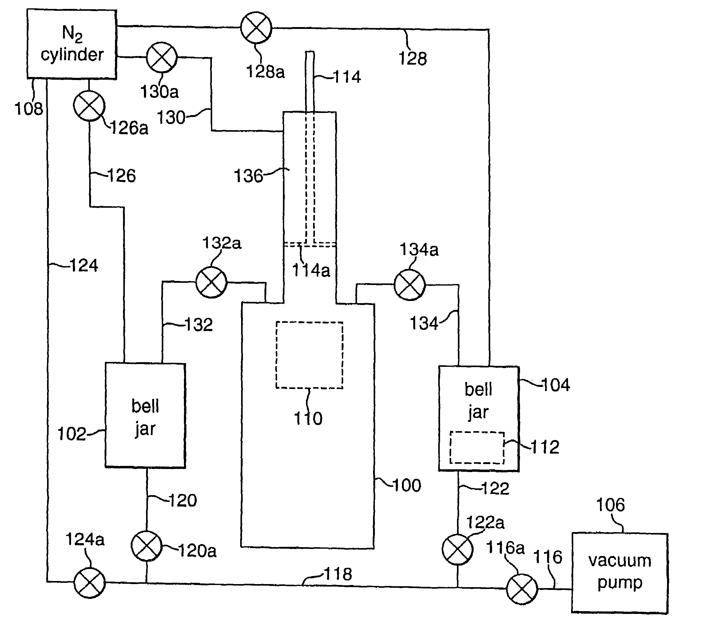
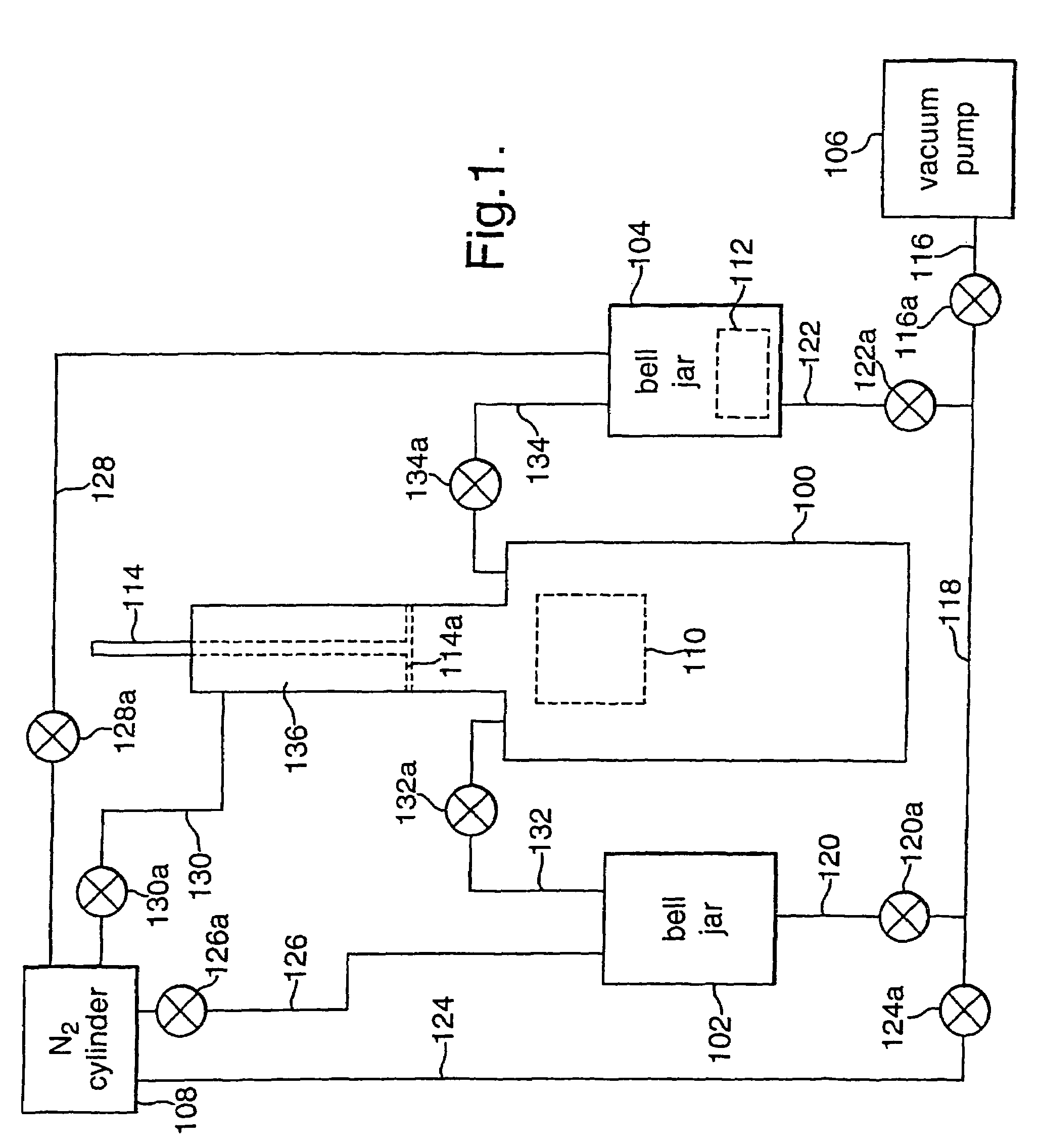
[0027]As can be seen from FIG. 1, the apparatus shown comprises a pressure vessel 100, a pair of bell jars 102 and 104, a vacuum pump 106 and a nitrogen cylinder 108, all connected through various lines and valves. The component 110 to be potted resides in the pressure vessel 100. The component in this example is an electronic device, although the invention may be used with many other types of components. Initially, the potting compound 112 (10:1 by weight of the component 110) resides in a second pressure vessel, namely the bell jar 104. In this embodiment, the potting compound 112 used was a silicone elastomer, but other potting compounds such as polyesters may be suitable.

[0028]The pressure vessel 100 is provided with a piston 114 operable to change the internal volume of the pressure vessel 100: initially, the piston 114 is positioned in a retracted position to allow a gap of 30 mm in the base of the piston 114 (not illustrated). To ensure the piston 114 remains in the retracted...


PUM

PropertyMeasurementUnit
pressureaaaaaaaaaa
pressureaaaaaaaaaa
pressureaaaaaaaaaa

Abstract

This invention relates to a method of potting a component, namely encasing a component (110) in a potting compound (112) with, optionally, all or some of the voids in the component also being filled with potting compound. In particular, the present invention relates to potting a component that will be subject to high electric field strengths in use. The method comprises introducing an inert gas into a first pressure vessel (100) containing the component to be potted thereby to create an inert environment, introducing a potting compound into the first pressure vessel and allowing the potting compound to cure in the inert environment.

Description

[0001]This invention relates to a method of encasing a component in a potting compound with, optionally, all or some of the voids in the component also being filled with potting compound.BACKGROUND OF THE INVENTION[0002]Typically, a fluid such as a silicone elastomer or a polyester is introduced to the component to be potted such that the component is enveloped in the potting compound. The potting compound is then allowed to cure to form a solid around and, possibly, within the component. Excess potting material can then be removed as required.[0003]In particular, the present invention relates to potting a component that will be subject to high electric field strengths in use. For example, electrical or electronic devices or parts thereof are often potted in a dielectric material, i.e. the potting compound then forms a dielectric between conducting components. This is advantageous because the potting compound usually offers greater resistance to electrical breakdown when exposed to ...

Claims


Application Information

Patent Timeline
Patent Type & Authority Patents(United States)
IPC IPC(8): B65B1/04B29C39/02B29C39/24B29C39/42H01L21/56
CPCB29C39/42H01L21/56B29C2791/005B29C2791/006B29K2995/0006B29L2031/3406H01L2924/0002H01L2924/00
Inventor GARNER, PAUL ANTHONY JAMESMOORE, IAN ANTHONY
Owner BAE SYSTEMS PLC
Why Eureka
Try Eureka