Sealing of electronic device using absorbing layer for glue line

a technology of absorbing layer and glue line, which is applied in the direction of electromagnetic transmission, thermoelectric devices, transmission, etc., can solve the problems of component warpage, damage to the absorber of supplied ir radiation,

a technology of absorbing layer and glue line, which is applied in the direction of electromagnetic transmission, thermoelectric devices, transmission, etc., can solve the problems of component warpage, damage to the absorber of supplied ir radiation,

US7078726B2Active Publication Date: 2006-07-18DOLYA HOLDCO 5 LTD

Image

  • Sealing of electronic device using absorbing layer for glue line
  • Sealing of electronic device using absorbing layer for glue line
  • Sealing of electronic device using absorbing layer for glue line

Examples


Embodiment Construction

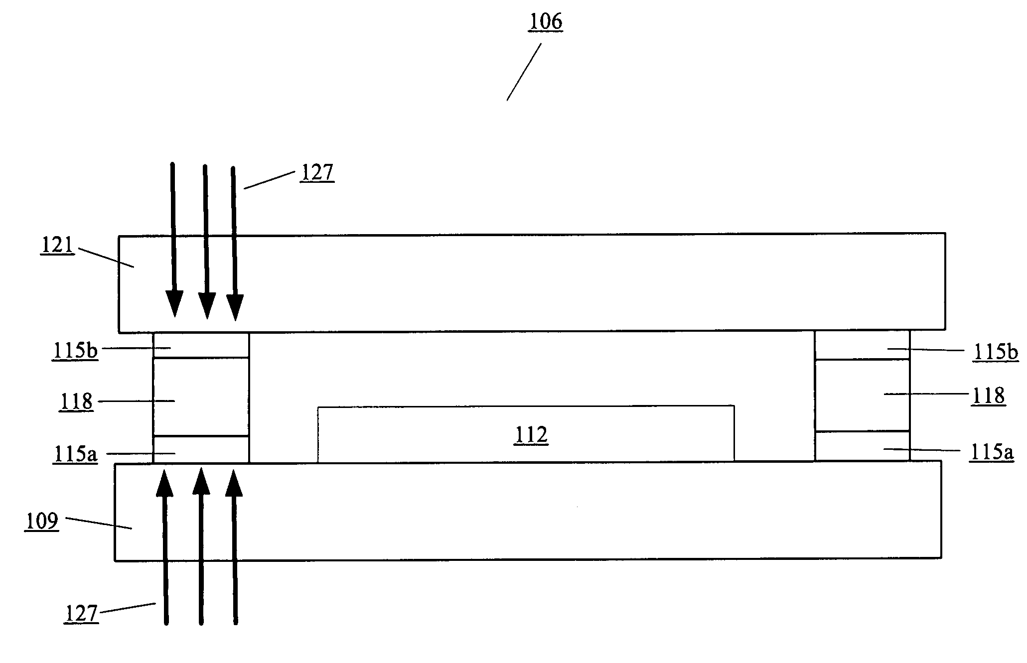
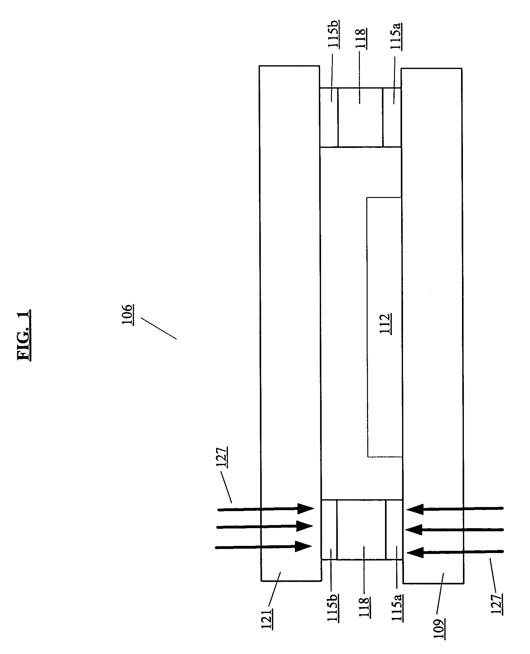
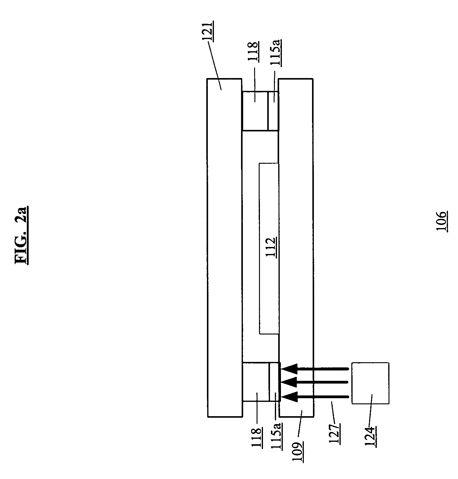
[0017]In an embodiment of this invention, a first absorbing layer is on a substrate and / or a second absorbing layer is on a heat-activated adhesive. If the IR source that supplies IR radiation is present on a substrate-side, then an absorption percentage of the substrate is less than an absorption percentage of the first absorbing layer if present and less than an absorption percentage of the second absorbing layer if present. If the IR source that supplies IR radiation is present on an “encapsulation cover”-side, then an absorption percentage of the encapsulation cover is less than an absorption percentage of the first absorbing layer if present and less than an absorption percentage of the second absorbing layer if present. The substrate and the encapsulation cover have a low thermal conductivity. When the substrate and the encapsulation cover are brought together so as to seal the organic electronic device, the first absorbing layer if present is in proximity to the heat-activate...


PUM


Abstract

In one embodiment of the invention, a first absorbing layer is on a substrate and / or a second absorbing layer is on a heat-activated adhesive. If the IR source that supplies IR radiation is present on the substrate-side, then the absorption percentage of the substrate is less than the absorption percentage of the first absorbing layer if present and less than the absorption percentage of the second absorbing layer if present. If the IR source that supplies IR radiation is present on the “encapsulation cover”-side, then the absorption percentage of the encapsulation cover is less than the absorption percentage of the first absorbing layer if present and less than an absorption percentage of the second absorbing layer if present. The substrate and the encapsulation cover have a low thermal conductivity.

Description

BACKGROUND OF THE INVENTION[0001]An organic electronic device such as, for example, an organic light emitting diode (“OLED”) display, an OLED light source for area illumination, an organic light sensor array, an organic transistor array, or an organic solar cell array require protection from oxygen and moisture in the atmosphere, and therefore employ some form of encapsulation. One common procedure to encapsulate the organic electronic device is to sandwich it between a substrate and an encapsulation cover, and an adhesive around the perimeter of the device holds together the substrate and the encapsulation cover such that there is a continuous perimeter seal around the device.[0002]Typically, the substrate and the encapsulation cover are sealed together using UV-curable adhesive or thermal-cure adhesive. In many cases, use of the thermal-cure adhesive would be advantageous. Thermal-cure adhesive provides many advantages such as good performance and predictable results due to the ma...

Claims


Application Information

Patent Timeline
18 Jul 2006
Publication
US7078726B2
IPC
H01L35/24; H10N10/856
CPC
H01L21/50; H01L51/448; H01L51/5237; H01L23/10; H01L2924/0002; Y02E10/549; H01L2924/00; H10K30/88
Inventors
PICHLER, KARL; FRISCHKNECHT, KYLE D.