Bandwidth properties of LC-SLMs for telecommunication applications with particular third compensator

a technology of telecommunication applications and bandwidth properties, applied in optics, instruments, optical elements, etc., can solve the problems of limited performance of channel equalizers, many designs developed for display applications are not particularly relevant to the needs of telecom applications, and prior art filtering and add/drop components have difficulty in meeting the optical performance requirements of next-generation all-optical networks, etc., to minimize the contribution of temperature-dependent lc birefringence, simplify electronic corrections, and high extinction

Inactive Publication Date: 2006-07-18
KEWITSCH ANTHONY S
View PDF6 Cites 16 Cited by
  • Summary
  • Abstract
  • Description
  • Claims
  • Application Information

AI Technical Summary

Benefits of technology

[0015]Thus in accordance with the invention the intrinsic properties of optical modulators such as liquid crystals and optical elements such as quartz which are relatively thermally and optically stable are employed, for their own properties and in relation to each other, to approach optimal properties for specific operating conditions. These properties include not only wavelength flattening and athermalization, but more specific operative goals such as high extinction in an individual device or in multiple devices in an array (channel blocking), full transmission in one device or an array, linear attenuation or modulation in analog operation. Components can be employed to best advantage in introducing retardation, as by orienting the optical axes of elements in relation to the polarization of incident light and each other so as to use the most stable properties of elements and / or simplify the electronic corrections that are needed. Thus, in accordance with the invention the compensator / LC device can be arranged to minimize the contribution of the temperature dependent LC birefringence and maximize the contribution of the temperature independent quartz with operating in the high extinction state. Conversely, when in the high extinction state the combination does not require active electronic feedback to maintain the operating conditions in range.

Problems solved by technology

Optical communication systems impose a number of particular and demanding requirements on DWDM wavelength filters and network devices.
For example, at 25 and 50 GHz separations, prior art filtering and add / drop components have difficulty in meeting the optical performance requirements of next generation all-optical networks.
At present, the performance of channel equalizers is limited by the fact that liquid crystal spatial light modulators commonly used for fiberoptic applications exhibit wavelength and temperature dependence.
However, the numerous designs developed for display applications are not particularly relevant to the needs of telecom applications.
The extension of visible display techniques to achromatize infrared LC-SLMs does not provide the performance required for these unique fiberoptic applications.
This interpolation further reduces the accuracy of the system performance.
This level of blocking places extreme demands on the precision in which the retardation of individual LC-SLM pixels must be controlled.
The wavelength dependence of extinction within the C band varies, for example, between 1565, 1545, and 1530 nm, which adds complexity in the look up table algorithms and drive electronics, compromising the precision in which the attenuation and extinction can be set across a wide range of temperatures and wavelengths.
This reduces the flexibility in the design of the overall system hardware, because drive electronics components are available for output voltages of 5, 8, 10, and 22 volts, wherein increasing the output voltage increases cost, size, power consumption and reduces the range of component selection.

Method used


Image

  • Bandwidth properties of LC-SLMs for telecommunication applications with particular third compensator
  • Bandwidth properties of LC-SLMs for telecommunication applications with particular third compensator
  • Bandwidth properties of LC-SLMs for telecommunication applications with particular third compensator

Examples


example 1

Wavelength Flattened LC-SLM with Thin Compensator Plate

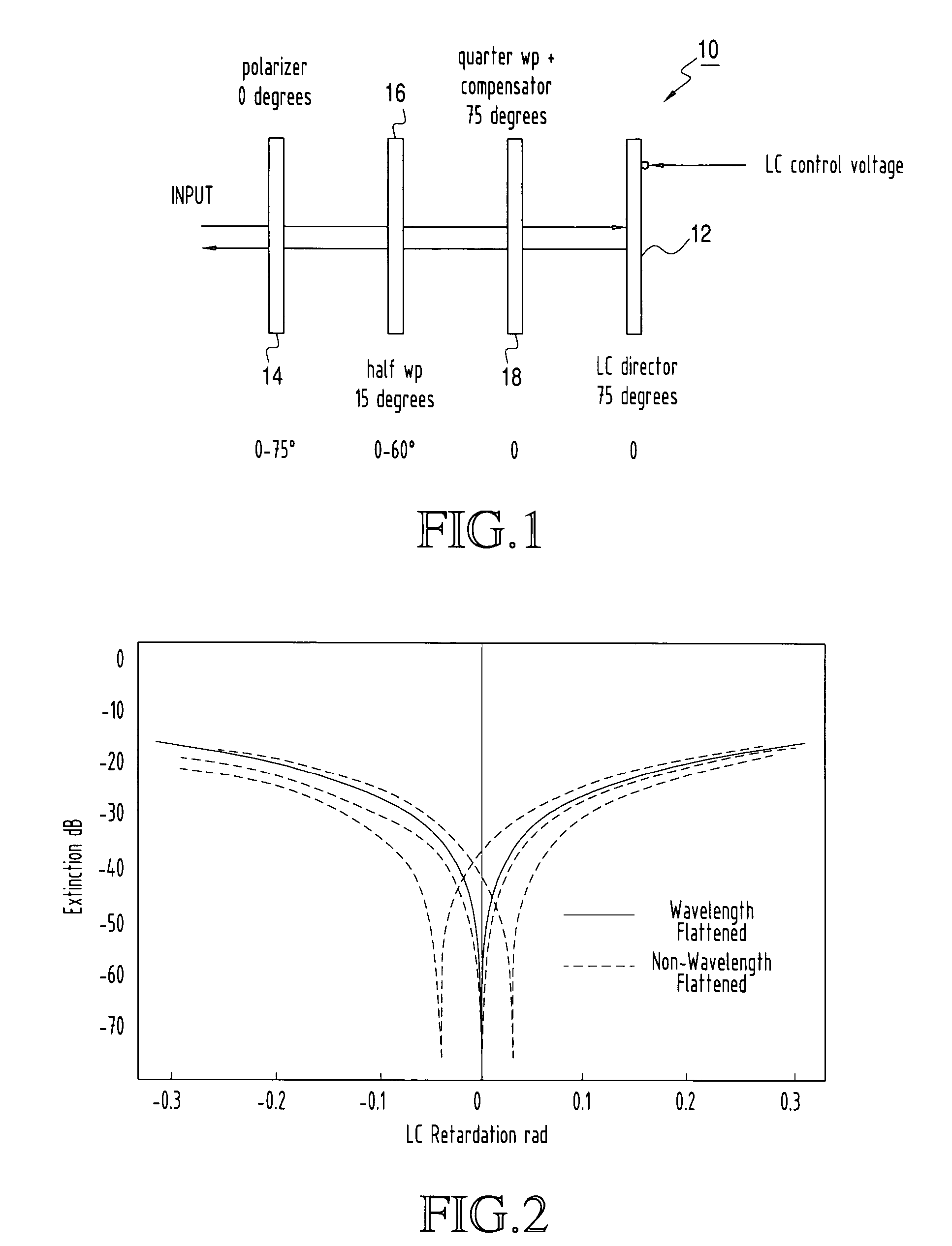
[0045]For a wavelength flattened cell 16, the orientations of the waveplates and the optical axis of the LC-SLM are noted in FIG. 1. In general, only the relative angles of the elements are relevant. If the input polarization is maintained at 0 degrees, then the angle of the fast axis of the half wave plate 16 is 15 degrees, the angle of the fast axis of the quarter wave plate 18 is 75 degrees, and the angle of the slow axis of the LC-SLM 12 is 75 degrees. Typically, the polarization of the beam as it enters the modulator subassembly is aligned at either 0 (90) degrees or 45 (−45) degrees, as determined by the polarizing element 14. The polarizer 14 orientation establishes a reference angle, to which the orientations of the associated wave plates 16 and 18 and the rubbing direction of the LC cell 12 are related. The contrast in linearity of wavelength response between a wavelength flattened unit (solid line) and a non-wavelength...

example 2

Wavelength Flattened LC-SLM without Thin Compensator Plate

[0054]In an alternate embodiment, FIG. 10, the compensator element can be incorporated into the quarter wave plate by making the quarter wave plate 18″ thicker. The quarter wave plate 18″ retardation is increased by the amount needed to shift the LC retardation response of FIG. 11 to that of FIG. 12. The fast axis of the quarter wave 12″ plate is optimally aligned parallel to the slow axis of the LC-SLM 12′. A typical quartz quarter wave plate 18″ at 1550 nm is 45 um thick. To add approximately 50 to 100 nm of retardation, about 5 to 10 um of additional quartz is needed. Therefore, the combination quarter wave plate and compensator is about 54 um thick. This compensation approach requires that the optical axes of the LC-SLM 12′ and compensating quarter wave plate 18″ be parallel to one another, and be aligned at 60 degrees to the half wave plate 16. For a polarizer or PBD 22 oriented at 0 degrees, the LC-SLM 12′ and quarter w...

example 4

LC-SLM Array

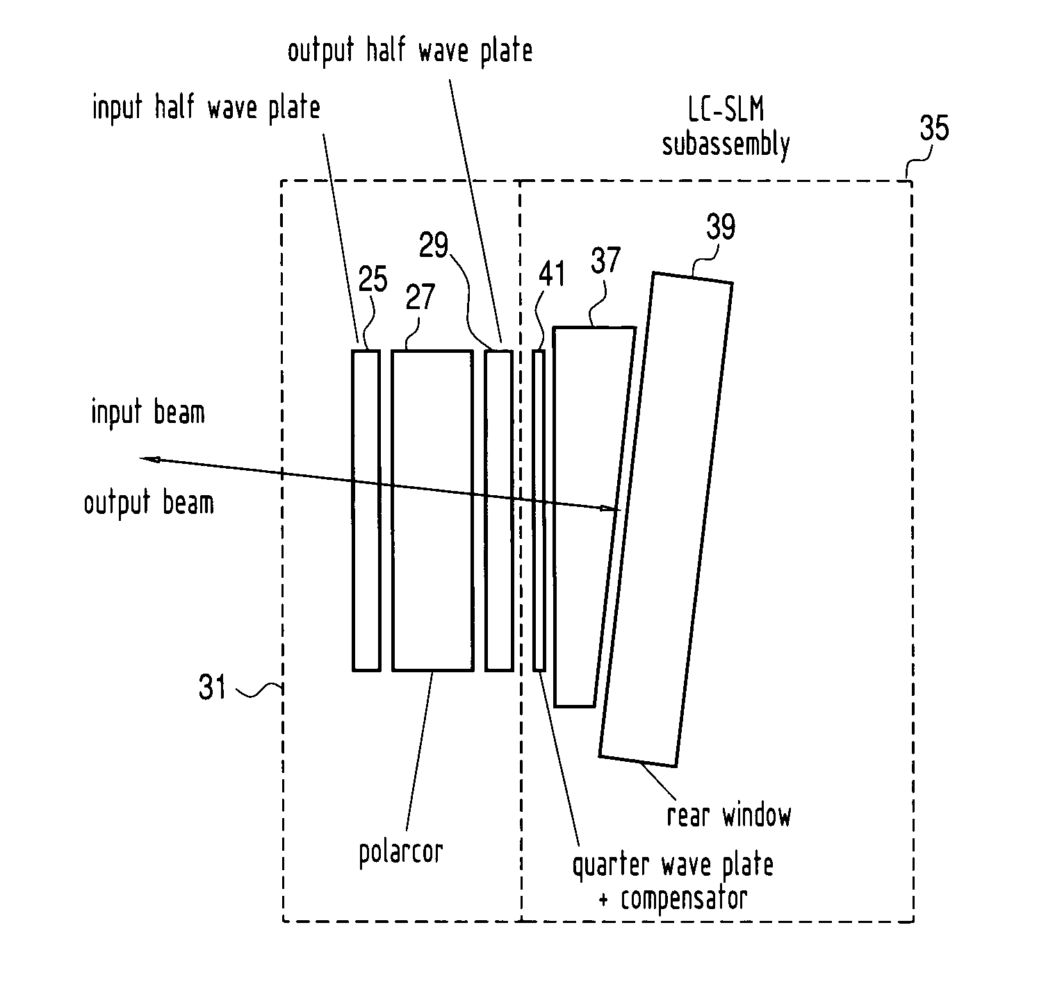
[0060]The previously referenced Kewitsch et al. patent provides an example of an advanced LC-SLM modulator array and system for precise and high efficiency manipulation of the channels of a WDM configuration. In this arrangement, as shown in FIG. 16, an LC-SLM 35 unit which represents a single channel of a multichannel array dispersed in the vertical direction relative to the paper includes, within the subassembly 35, a wedge 37 immediately in front of the liquid crystal module 39 and after a frontal quarter wave plate and compensator 41. The input beam is a single wavelength beam derived from a WDM input by diffractive optics beam dispersing system and directed, by polarization optics, as described in the prior application, at a small angle of inclination to the receiving face of the liquid crystal cell. As described in the previously referenced application, for high efficiency polarization sensitive optics is used in a way which introduces slight height differentiation...


PUM

PropertyMeasurementUnit
angleaaaaaaaaaa
edge wavelengthsaaaaaaaaaa

Abstract

Intrinsic material and optical properties of liquid crystal units, such as variable response to wavelength and temperature variations, are accommodated in accordance with the invention by introducing at least a pair of wave plates of different thicknesses which, together with the retardation introduced by the liquid crystal, serve to broaden the wavelength of response in fashion which also athermalizes the response. Specific retardations and angles of inclination relative to the input polarization are employed for overcoming these nonlinearlities.

Description

REFERENCE TO PRIOR APPLICATION[0001]This application relies for priority on provisional application Ser. No. 60 / 393,529, filed Jul. 15, 2002 and entitled “Wavelength Flattened LC-SLMs for Telecommunications Applications” and patent application Ser. No. 10 / 209,879 filed Aug. 2, 2002 by A. S. Kewitsch et al. and entitled “Liquid Crystal Modulators and Polarization Diversity Optics for Optical Communications”.FIELD OF THE INVENTION[0002]This invention relates to optical communications devices and methods and more particularly to improving the optical and other performance characteristics of liquid crystal spatial light modulators for use in optical communication systems.BACKGROUND OF THE INVENTION[0003]Next generation optical networks are focused on economically exploiting the inherent bandwidth of optical fiber. Optical routing, agile wavelength provisioning and wavelength management are key characteristics of these next generation communications systems. The ability to perform attenu...

Claims


Application Information

Patent Timeline
Patent Type & Authority Patents(United States)
IPC IPC(8): G02B27/10G02F1/13363G02F1/31
CPCG02F1/13363G02F1/31G02F2413/08G02F2203/07G02F2203/60G02F2001/133638G02F1/133638
Inventor KEWITSCH, ANTHONY S.
Owner KEWITSCH ANTHONY S
Why Eureka
Try Eureka