Method and device for instrument, bone segment, tissue and organ navigation

a technology for organs and instruments, applied in the field of methods and devices for instruments, bone segments, tissue and organ navigation, can solve the problems of unnecessarily invasive procedures, expensive cad-cam models to be produced, etc., and achieve the effects of facilitating safe and reproducible navigation, reducing costs, and less invasiveness

Inactive Publication Date: 2006-07-18
LB MEDICAL GMBH
View PDF9 Cites 12 Cited by
  • Summary
  • Abstract
  • Description
  • Claims
  • Application Information

AI Technical Summary

Benefits of technology

[0005]It is an object of the present invention to provide a method and a device for instrument, bone segment, tissue and organ navigation, which operates without auxiliary devices, such as templates, and facilitates a safe and reproducible navigation.
[0006]By using optical measurements and by referencing the operating site via the characteristic surface of a soft tissue envelope or a bone surface, the cost can be reduced significantly and the surgical access path can be significantly less invasive. For a bone segment navigation with the present invention, the 3-D localization markers can be individually secured on a bone segment independent of a template—such as a screw, which opens additional possibilities for a minimally-invasive surgical procedure.
[0007]Optical referencing between the data set, the operating site and the 3-D localization markers is also faster and more precise than the aforedescribed referencing method that uses anatomical indicia and implants, because large surface structures in a patient data set (for example MRT or CT) can be imaged more exactly and reproduced than small, singular reference points.

Problems solved by technology

The method has the disadvantage that an expensive CAD-CAM model has to be produced from a patient data set before an individual template can be manufactured.
With many surgical procedures, large areas of bone have to be exposed for applying the individual surface template, which makes the procedure unnecessarily invasive.

Method used


Image

  • Method and device for instrument, bone segment, tissue and organ navigation
  • Method and device for instrument, bone segment, tissue and organ navigation
  • Method and device for instrument, bone segment, tissue and organ navigation

Examples


Embodiment Construction

[0019]The invention will be described hereinafter in more detail with reference to a first embodiment.

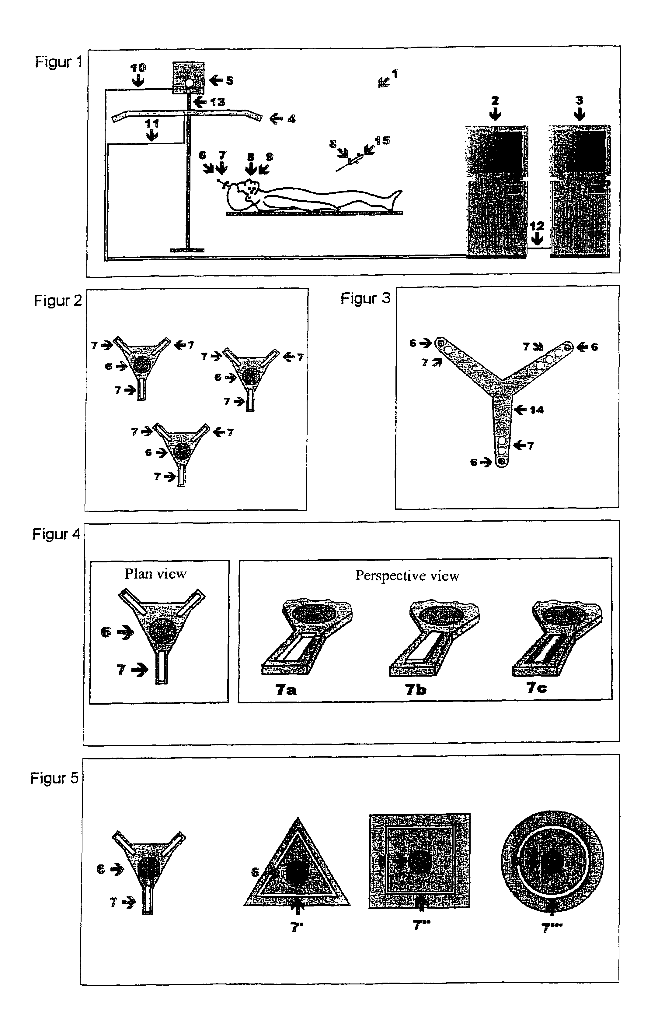
[0020]The entire system 1 is used for optical referencing between an operating site, a patient data set and 3-D markers.

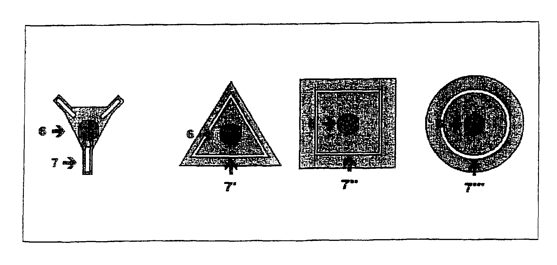
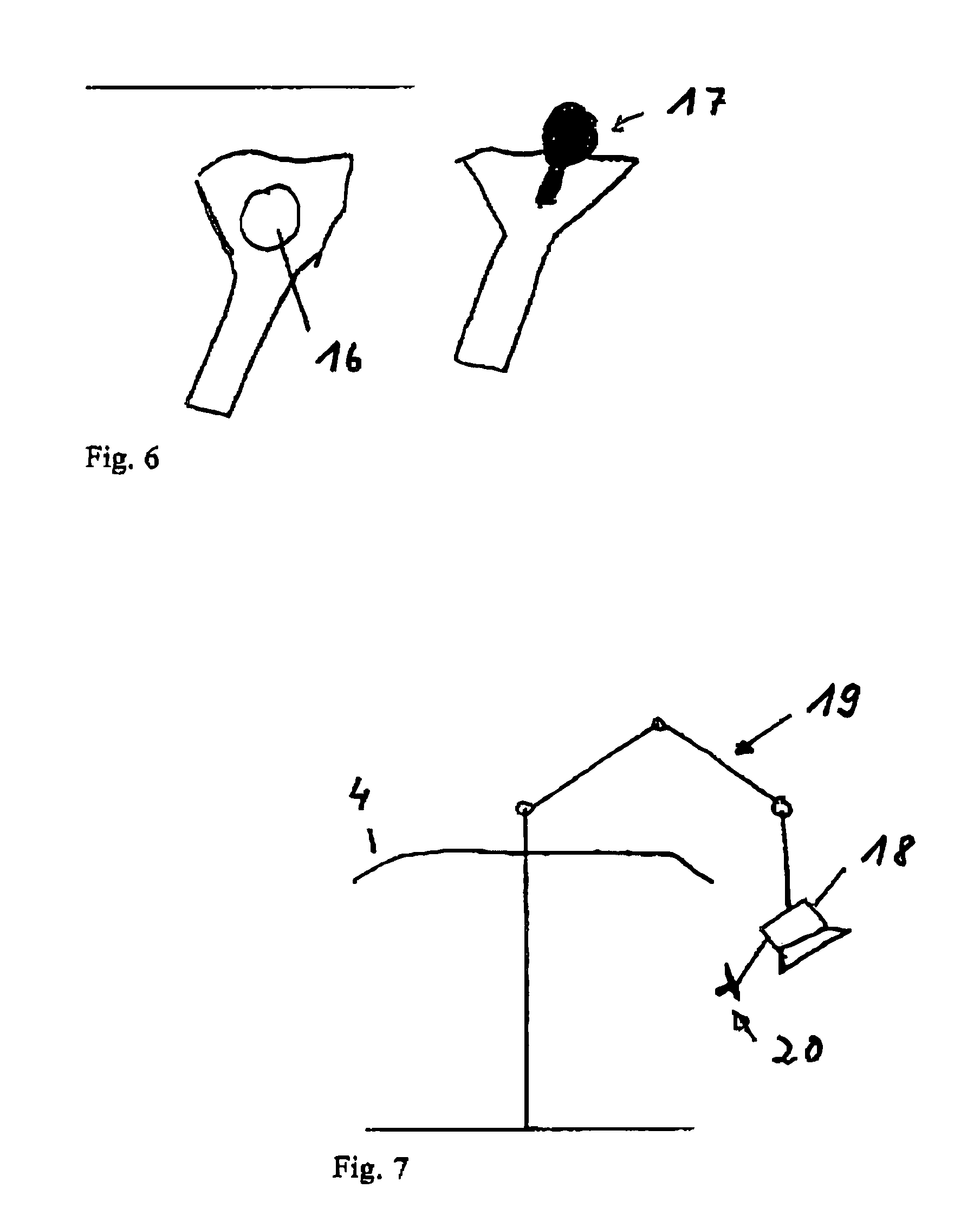
[0021]An optical 3-D scanner 5 is attached to a position detection unit 4 via a coupling device 13. The position detection unit 4 can acquire, for example, infrared signals, ultrasound signals or electromagnetic signals and allows the determination of three-dimensional coordinates of a corresponding 3-D marker 6 (for example: ultrasound transmitter, infrared transmitter, electromagnetic transmitter and / or reflectors 17 for all types of waves, ultrasound, infrared, radar, etc.). The 3-D scanner 5 (for example a 3-D laser scanner 5 or a radar unit 5a) can detect the shape and color of surfaces (for example 7), but not the signals from the 3-D markers 6. The signals from the 3-D markers 6 can be transmitted actively, for example with an LED, or passively, for example ...


PUM


Abstract

The invention relates to a method and device for referencing between a data set, which describes geometrically the spatial model of a body, and the real physical environment in which the body is placed. A three-dimensional position reference body is used on the real body. The position reference body has one or more elementary bodies or markers whose 3-dimensional position can be detected with sensors and which define a fixed geometric reference with respect to the center of gravity of the body or to other body reference volumes. For registration, the position reference body and/or its elementary bodies are correlated in the data model and in the physical world.

Description

BACKGROUND OF THE INVENTION[0001]A patient data set and an operating site during surgery are typically referenced to each other by using either anatomical indicia or—before an image data set is created—implants (bone or skin markers) that are applied to the patient. The implants are indicated simultaneously with an input device at a workstation and with a localization system on the patient.[0002]A more general task relates to referencing between a data set (which describes geometrically the spatial model of a body) and the real physical environment in which the actual body is placed. For referencing, a three-dimensional position reference body is used on or applied to the real body. The position reference body consists of one or more elementary bodies (markers) whose 3-dimensional position can be detected with sensors and which define a fixed geometric reference with respect to the center of gravity of the body or to other reference volumes of the body. For the purpose of registrati...

Claims


Application Information

Patent Timeline
Patent Type & Authority Patents(United States)
IPC IPC(8): A61B5/05A61B17/30A61B34/20A61B90/00A61B90/96
CPCA61B19/5244A61B19/54A61B19/50A61B2017/306A61B2019/442A61B2019/5255A61B2019/5479A61B2019/5265A61B2019/5272A61B2019/5429A61B2019/5437A61B2019/5445A61B2019/5257A61B34/10A61B34/20A61B90/39A61B90/96A61B2034/2055A61B2034/2057A61B2034/2065A61B2034/2072A61B2090/3929A61B2090/3937A61B2090/3945A61B2090/3979
Inventor MARMULLA, RUEDIGERLUETH, TIM
Owner LB MEDICAL GMBH
Why Eureka
Try Eureka