Exhaust gas recirculation system for internal combustion engine

a technology internal combustion engine, which is applied in the direction of exhaust treatment electric control, machines/engines, mechanical equipment, etc., can solve the problems of contaminated intake passage, high temperature of exhaust gas, and recirculation of exhaust gas, so as to improve engine fuel efficiency, reduce the contamination of intake passage, and increase the effect of exhaust gas recirculation

Inactive Publication Date: 2006-07-25
NISSAN MOTOR CO LTD
View PDF9 Cites 13 Cited by
  • Summary
  • Abstract
  • Description
  • Claims
  • Application Information

AI Technical Summary

Benefits of technology

[0010]Conversely, when the exhaust gas is drawn from a portion of the exhaust passage located downstream of the catalytic converter, the exhaust gas passes through the catalytic converter before it is recirculated to the intake passage and, thus, there is less contamination of the intake passage. However, the heat generated by the reactions inside the catalytic converter causes the temperature of the exhaust gas to become high and there are times when not much exhaust gas can be recirculated in view of the heat resistance of the intake passage and the heat resistance of the flow regulating valve provided in the recirculation passage, such as when the internal combustion engine is running under high load and high rotational speed conditions. In such cases, a chance to improve the fuel efficiency of the engine with increased exhaust gas recirculation is forfeited in order to protect the intake passage and the flow regulating valve from heat damage.
[0011]The object of the present invention is to provide an internal combustion engine configured to enable a large amount of exhaust gas to be recirculated to the intake passage while reducing contamination of the inside of the intake passage caused by the recirculated exhaust gas and preventing damage to the intake passage caused by the heat of the recirculated exhaust gas.

Problems solved by technology

It has been discovered that in engines configured to improve fuel efficiency by recirculating exhaust gas drawn from a portion of the exhaust passage located upstream of the catalytic converter, the recirculated exhaust gas introduced into the intake passage has not passed through the catalytic converter and there is the possibility that the recirculated exhaust gas will react with blow-by gases and cause the intake passage to become contaminated.
However, the heat generated by the reactions inside the catalytic converter causes the temperature of the exhaust gas to become high and there are times when not much exhaust gas can be recirculated in view of the heat resistance of the intake passage and the heat resistance of the flow regulating valve provided in the recirculation passage, such as when the internal combustion engine is running under high load and high rotational speed conditions.

Method used


Image

  • Exhaust gas recirculation system for internal combustion engine
  • Exhaust gas recirculation system for internal combustion engine
  • Exhaust gas recirculation system for internal combustion engine

Examples


Embodiment Construction

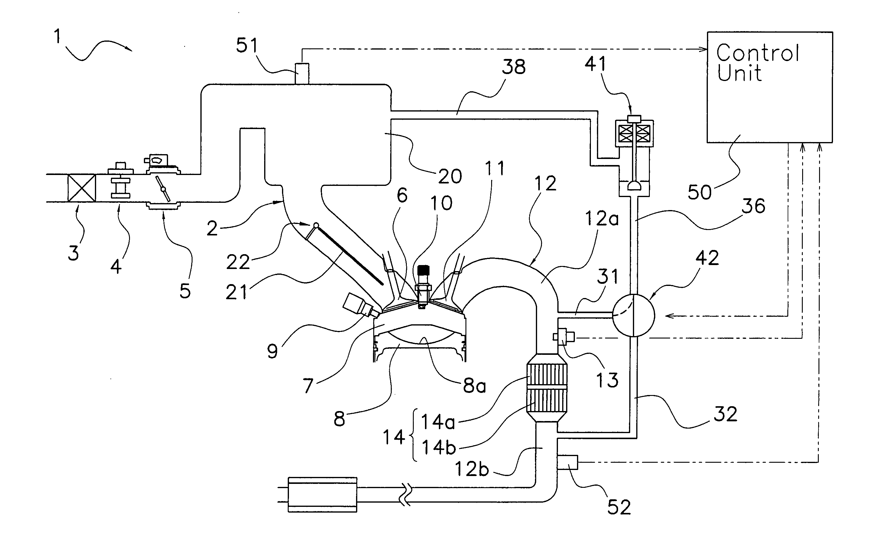
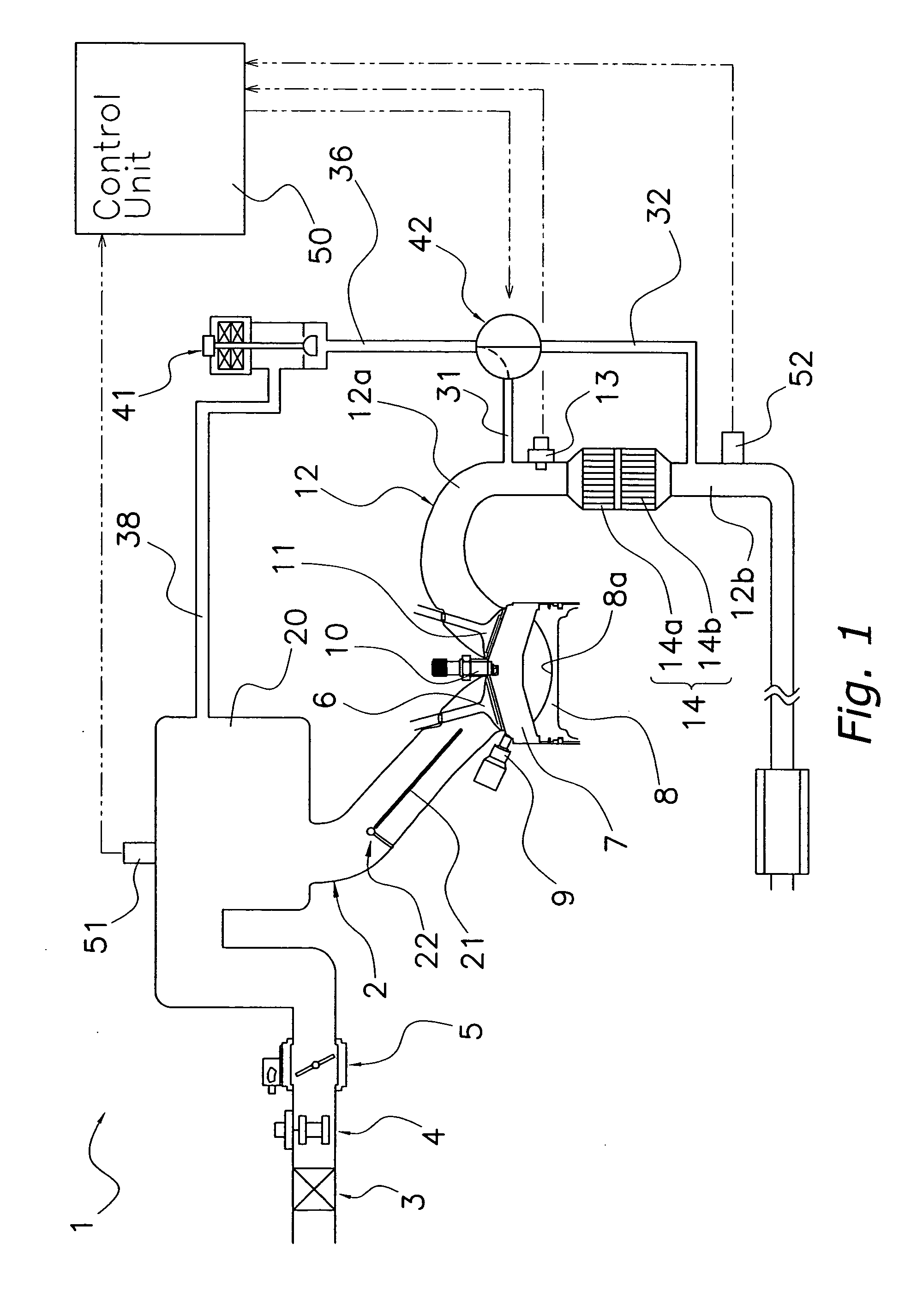
[0026]Selected embodiments of the present invention will now be explained with reference to the drawings. It will be apparent to those skilled in the art from this disclosure that the following descriptions of the embodiments of the present invention are provided for illustration only and not for the purpose of limiting the invention as defined by the appended claims and their equivalents.

[0027]Referring initially to FIG. 1, an internal combustion engine 1 is illustrated that is configured and arranged to include an exhaust gas recirculation system in accordance with a first embodiment of the present invention. Basically, the engine 1 includes an intake passage 2, an air cleaner 3, an air flow meter 4, an electronically controlled throttle valve 5, a plurality of intake valves 6, a combustion chamber 7, a fuel injection valve 9, a spark plug 10, a plurality of exhaust valves 11, an exhaust passage 12, an exhaust gas air-fuel ratio sensor 13 and a catalytic converter unit 14. It will...


PUM


Abstract

An exhaust gas recirculation system is configured to recirculate a large amount of exhaust gas to an engine intake passage while reducing contamination inside the intake passage caused by the recirculated exhaust gas and prevent damage to the intake passage caused by the heat of the recirculated exhaust gas. A first recirculation path recirculates exhaust gas from an upstream section of the exhaust passage located upstream of a catalytic converter unit. A second recirculation path recirculates exhaust gas from a downstream section of the exhaust passage located downstream of the catalytic converter unit. A control unit is provided that controls the switching of a selector valve between the first and the second recirculation paths based on the temperature of the recirculated exhaust gas.

Description

BACKGROUND OF THE INVENTION[0001]1. Field of the Invention[0002]The present invention relates to an exhaust gas recirculation system for an internal combustion engine. More particularly, the present invention relates to an exhaust gas recirculation system for an internal combustion engine having a catalytic converter provided in the exhaust passage.[0003]2. Background Information[0004]Exhaust gas recirculation systems configured to recirculate a portion of the exhaust gas from automobile engines and other internal combustion engines to the intake passage of the engine have been known for some time.[0005]For example, the internal combustion engine disclosed in Japanese Laid-Open Patent Publication No. 2003-83050 is configured to recirculate exhaust gas from a portion of the exhaust pipe (exhaust passage) located downstream of the catalytic converter to the intake pipe (intake passage) using an EGR pipe (recirculation passage).[0006]There are also automobile engines that are configure...

Claims


Application Information

Patent Timeline
Patent Type & Authority Patents(United States)
IPC IPC(8): F02M25/06F01N3/08F01N11/00F01N13/02F02B27/02F02B29/04F02B31/08F02D21/08F02M25/07
CPCF01N3/0814F01N13/009F01N11/002F02B29/0418F02B31/085F02M25/0718F02M25/0727F02M25/0735F02M25/0738F02M25/0744F01N3/0842F02M25/0796Y02T10/121Y02T10/146Y02T10/47F02M26/15F02M26/23F02M26/30F02M26/33F02M26/38F02M26/71Y02T10/12Y02T10/40
Inventor FUKUZUMI, MASAHIROIRIYA, YUICHIOKAMOTO, SHINICHI
Owner NISSAN MOTOR CO LTD
Why Eureka
Try Eureka