Electrical actuator having a direct current motor

Active Publication Date: 2006-07-25
SOMFY ACTIVITES SA
View PDF12 Cites 1 Cited by
  • Summary
  • Abstract
  • Description
  • Claims
  • Application Information

AI Technical Summary

Benefits of technology

[0017]Starting from the prior art requiring no electrical energy storage battery, it has been observed in the context of the work leading to the present invention that miniaturizing a converter having sufficient power to simultaneously power a radio-wave receiver, logical control elements and, primarily, the DC electric motor, requires the presence of at least one controlled switch, with a predefined freque

Problems solved by technology

However, it is proving advantageous to replace such alternating current motors with permanent magnet DC motors, designed to operate at an extra low voltage (ELV), that is, more often than not, less than 48 V. Such motors are produced in very large quantities, in particular for automobile applications, and their cost is therefore low.
However, converting a low voltage AC electrical source into an extra low voltage DC source raises problems.
Indeed, the dimensions of the components required lead to a physical separation between the power supply converter and the actuator.
This separation is not practical: it means having to arrange a second location to accommodate the power supply module and, above all, having to provide a large section cable connecting line to power the DC motor.
This connecting line also presents the drawback of radiating interference generated by the electrical switching action of the motor commutator.
However, for issues of battery life and mainte

Method used


Image

  • Electrical actuator having a direct current motor
  • Electrical actuator having a direct current motor

Examples


Embodiment Construction

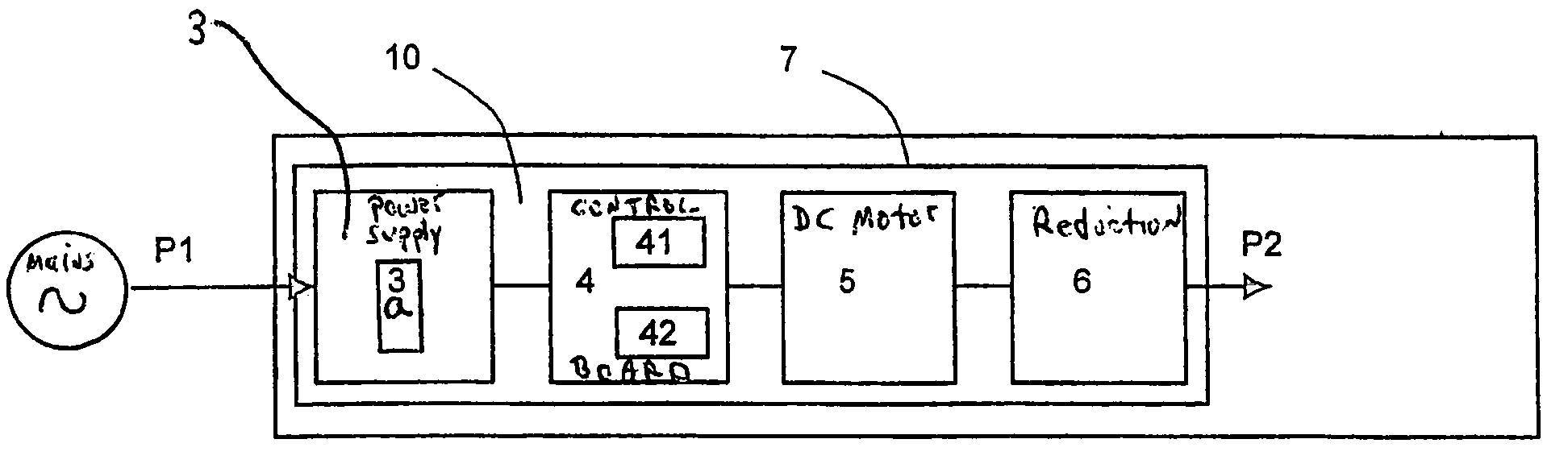
[0024]An actuator 10 represented in FIG. 1 takes from the AC electrical mains supply a power P1 to convert it into mechanical power P2 on an output shaft. The mechanical power P2 output is substantially lower than the electrical power P1 drawn at the input, because of losses within the actuator.

[0025]A step-down AC / DC converter 3, or power supply unit (referred to interchangeably herein) provides the required conversion from an AC low voltage into a DC extra low voltage. Naturally, its output voltage need not necessarily be strictly constant and major fluctuations associated with the frequency of the mains supply may even be accepted (for example, a ripple factor of 10 to 30%). For motor noise issues, there is nevertheless an interest in reducing this ripple.

[0026]This voltage is transmitted to an extra low voltage DC motor 5 via a control board 4 comprising in particular a radio-wave receiver 41. As in the above-mentioned prior art, the radio-wave receiver receives the control sign...


PUM


Abstract

An electrical mains-powered actuator designed to operate a closing, darkening or solar protection element, having in a common enclosure, a direct current motor, a board controlling the motor power supply and an AC/DC voltage converter, the control board including a radio-wave receiver, such that the voltage converter enables lowering of the voltage and includes at least one switch controlled at a frequency (F1) such that it is at most equal to twice the mains sector frequency or such that its ratio to the radio-wave receiver frequency (F0) ranges between 2.2 10−5 to 2.2 10−4.

Description

CROSS-REFERENCE TO RELATED APPLICATIONS[0001]This is a 371 national phase application of PC1 / IB03 / 04292 filled Sep. 9, 2003, claiming priority to French Patent Application No. 0212618 filed Oct. 10, 2002, the contents of which are incorporated herein by reference.FIELD OF THE INVENTION[0002]The invention relates to an electrical mains-powered actuator designed to operate a closing, darkening or solar protection element.BACKGROUND[0003]These actuators are often contained in a cylindrical enclosure when they control the movement of roller blinds and in a parallelepipedal enclosure when they control the movement of venetian blinds.[0004]Apart from very specific applications requiring an independent accumulator battery and / or solar panel type power supply, these actuators are powered from the low voltage (LV) AC mains supply (electric power grid, 110 to 230 V, 50 or 60 Hz, depending on countries) and the electric motors used in these actuators are normally of single-phase asynchronous t...

Claims


Application Information

Patent Timeline
IPC IPC(8): H04Q7/00H04Q9/00E06B9/32H02K11/00
CPCE06B9/32H02K11/0078H02K11/0073H02K11/33H02K11/35
Inventor BOUIX, MARCBRUNO, SERGE
Owner SOMFY ACTIVITES SA
Why Eureka
Try Eureka