Radio frequency low noise amplifier with automatic gain control

a low-noise amplifier and automatic gain control technology, applied in the field of amplifiers, can solve the problems of low-noise amplifiers, add to system costs, and inability to implement resistor t-networks accurately in conventional, low-cost cmos integrated circuits

Active Publication Date: 2006-07-25
SILICON LAB INC
View PDF21 Cites 35 Cited by
  • Summary
  • Abstract
  • Description
  • Claims
  • Application Information

AI Technical Summary

Problems solved by technology

However resistor T-networks exist as discrete components, which add to system cost.
Furthermore resistor T-networks are not very accurate when implemented in conventional, low-cost CMOS integrated circuits.

Method used


Image

  • Radio frequency low noise amplifier with automatic gain control
  • Radio frequency low noise amplifier with automatic gain control
  • Radio frequency low noise amplifier with automatic gain control

Examples


Embodiment Construction

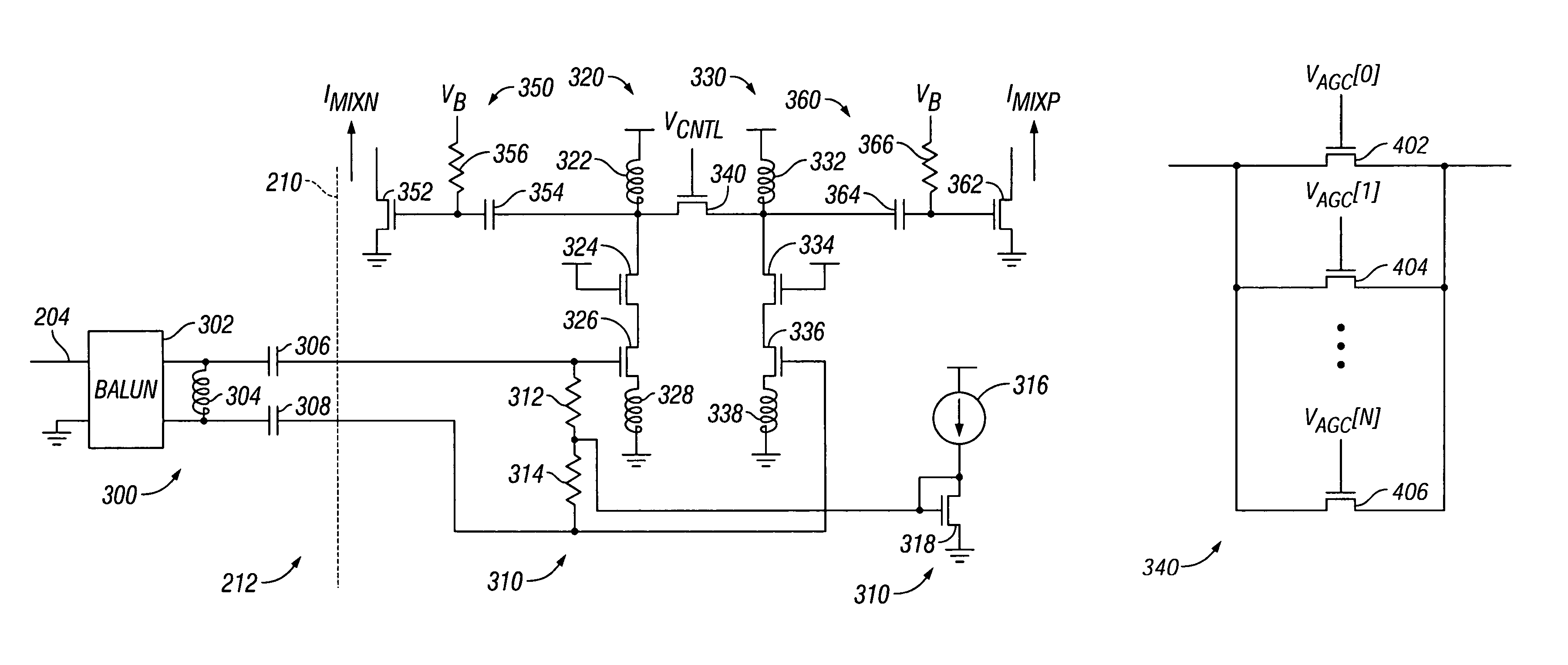
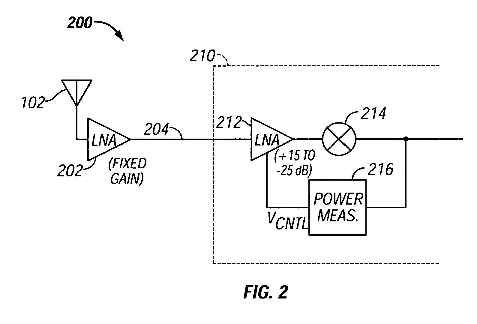
[0020]The following detailed description is merely exemplary in nature and is not intended to limit the invention or the application and uses of the invention. Furthermore, there is no intention to be bound by any expressed or implied theory presented in the preceding technical field, background, brief summary or the following detailed description.

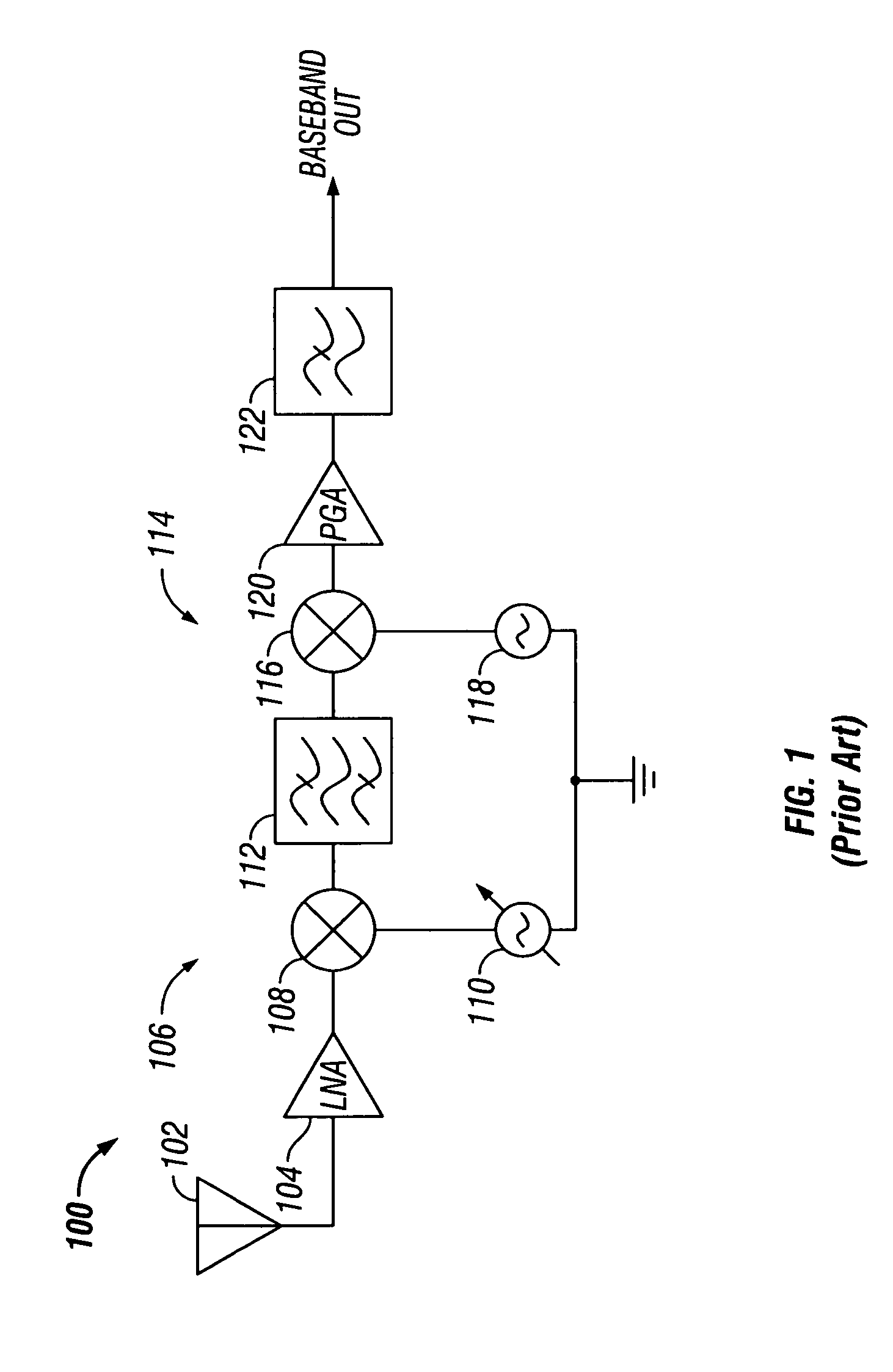
[0021]FIG. 1 illustrates in partial block diagram and partial schematic form a radio receiver 100 known in the prior art. Receiver 100 is a superheterodyne receiver that includes generally an antenna 102, a low noise amplifier labeled “LNA”104, an RF to IF mixer 106, a bandpass filter 112, an IF to baseband mixer 114, a programmable gain amplifier labeled “PGA”120, and a lowpass filter 122. Amplifier 104 has an input terminal connected to antenna 102, and an output terminal, and amplifies a broadband signal received on antenna 102 to provide an amplified signal to the output terminal thereof. Mixer 106 mixes the amplified signal to IF as f...


PUM


Abstract

A low noise amplifier (500) includes a first transconductance device (326) having a control electrode for receiving a first input signal, and a first current electrode; a first load device (322) having a first terminal coupled to a first power supply voltage terminal and a second terminal coupled to the first current electrode of the first transconductance device (326) and forming a first output voltage signal; a second transconductance device (336) having a control electrode for receiving a second input signal, and a second current electrode; a second load device (332) having a first terminal coupled to the first power supply voltage terminal and a second terminal coupled to the first current electrode of the second transconductance device (336) and forming a second output voltage signal; and an attenuation device (340) coupled between the first current electrodes of the first (326) and second (336) transconductance devices and having a control input terminal for receiving a control voltage thereon.

Description

[0001]This application is related to copending U.S. Provisional Application No. 60 / 503,010, which is entitled “SATELLITE RADIO RECEIVER” and was filed Sep. 15, 2003, and to U.S. Provisional Application No. 60 / 514,067, which is entitled “SATELLITE RADIO TUNER PRODUCT” and was filed Oct. 24, 2003, both of which are incorporated herein by reference in their entirety.TECHNICAL FIELD[0002]The present invention generally relates to amplifiers, and more particularly to low noise amplifiers for use in radio frequency equipment or the like.BACKGROUND[0003]Radio frequency (RF) devices transmit an information signal from one point to another by moving the information signal to a higher frequency range that is more suitable for transmission over the medium being used. This process is known as upconversion. As used herein, “radio frequency signal” means an electrical signal conveying useful information and having a frequency from about 3 kilohertz (kHz) to thousands of gigahertz (GHz), regardles...

Claims


Application Information

Patent Timeline
Patent Type & Authority Patents(United States)
IPC IPC(8): H03F3/45H03D7/14H03F1/26H03F3/193H03G1/00H03G7/00
CPCH03F1/26H03F3/193H03F3/45179H03G7/001H03G1/0023H03G1/0035H03F2200/06H03F2200/294H03F2203/45024H03F2203/45464H03F2203/45638H03F2200/372H03F3/45H03G1/00
Inventor KRONE, ANDREW W.
Owner SILICON LAB INC
Why Eureka
Try Eureka