Lithographic apparatus and device manufacturing method

a technology of lithographic equipment and manufacturing method, which is applied in the direction of electrical equipment, printers, instruments, etc., can solve the problems of difficult to accurately position the substrate and accurate positioning of the target portion of the substra

Active Publication Date: 2006-07-25
ASML NETHERLANDS BV
View PDF28 Cites 50 Cited by
  • Summary
  • Abstract
  • Description
  • Claims
  • Application Information

AI Technical Summary

Benefits of technology

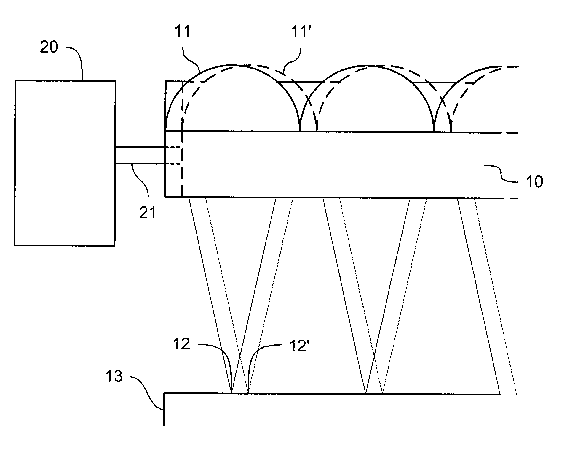
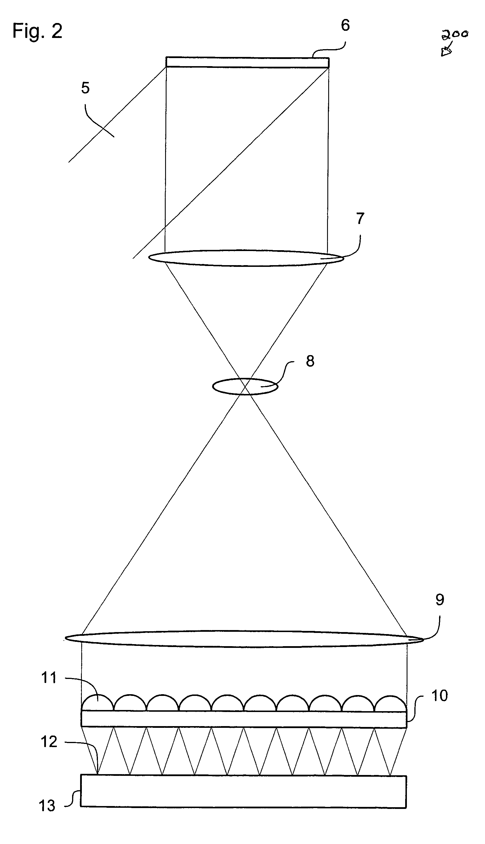
[0007]Embodiments of the present invention provide a system that can correctly position a pattern produced on a substrate.
[0011]By use of these adjustments, as appropriate, it is possible to compensate not only for positional errors of the target portion of the substrate relative to the substrate table, for example, but also for any local deformations of the substrate. Such deformation may result in, for example, the target portion of the substrate being out of the plane of the remainder of the substrate (i.e. displaced in a direction perpendicular to the plane of the substrate) or at an angle to it. Therefore, with the present invention, improved imaging of the pattern onto the substrate may be achieved if the substrate is not perfectly flat without requiring movement of the substrate itself.
[0012]The array of focusing elements may include a radiation blocking layer that is disposed between the focusing elements and prevents radiation within the patterned beam which is not incident on any one of the focusing elements from reaching the substrate. Consequently, when the array of focusing elements is moved relative to the array of individually controllable elements, radiation from one or more of the individually controllable elements associated with a first focusing element in the array of focusing elements will not be incident on another one of the focusing elements and hence will not be projected onto a different part of the target portion of the substrate than was intended. Thus, so-called “ghosting” will be reduced or prevented. Furthermore, the radiation directed onto the aperture associated with each focusing element may overfill the aperture. Accordingly as the array of focusing elements is moved, each aperture in the radiation blocking layer remains filled. Therefore, the intensity of the radiation directed to the substrate does not change due to the movement of the array of focusing elements. The radiation blocking layer may, for example, be formed from chromium.
[0014]A second actuator system may be provided for moving the second array of focusing elements relative to the second array of individually controllable elements. Consequently, it is possible to ensure that both patterned beams are correctly aligned with the respective portions of the substrate on which they are incident as well as relative to each other.
[0016]The apparatus may include a reference frame to which the actuator systems are mounted so that they can move the associated arrays of focusing elements relative to the reference frame. Thus, by knowing the position of the substrate or a portion thereof relative to the reference frame, it is possible to control the positions of each of the arrays of focusing elements relative to the substrate.
[0021]Preferably, the actuator system can be arranged to move the first light engine relative to the second light engine in at least one of the following: (1) in a first direction, substantially parallel to the face of the substrate on which the patterned beams are incident; (2) in a second direction, perpendicular to the first direction and substantially parallel to the face of the substrate on which the patterned beams are incident; (3) in a third direction, substantially perpendicular to the face of the substrate on which the patterned beams are incident; and (4) rotationally about one or more axes substantially parallel to the first, second and third directions. Accordingly, it is possible to ensure that the patterned beams each correctly position and align with the respective portion of the substrate on which they are incident, even if there are local deformations in the substrate.

Problems solved by technology

Such a size of substrate may make it difficult to accurately position the substrate.
Furthermore, especially with large substrates, while it may be possible to accurately position the substrate as a whole, this may not result in accurate positioning of the target portion of the substrate on which the patterned beam is to be projected.

Method used


Image

  • Lithographic apparatus and device manufacturing method
  • Lithographic apparatus and device manufacturing method
  • Lithographic apparatus and device manufacturing method

Examples


Embodiment Construction

Overview and Terminology

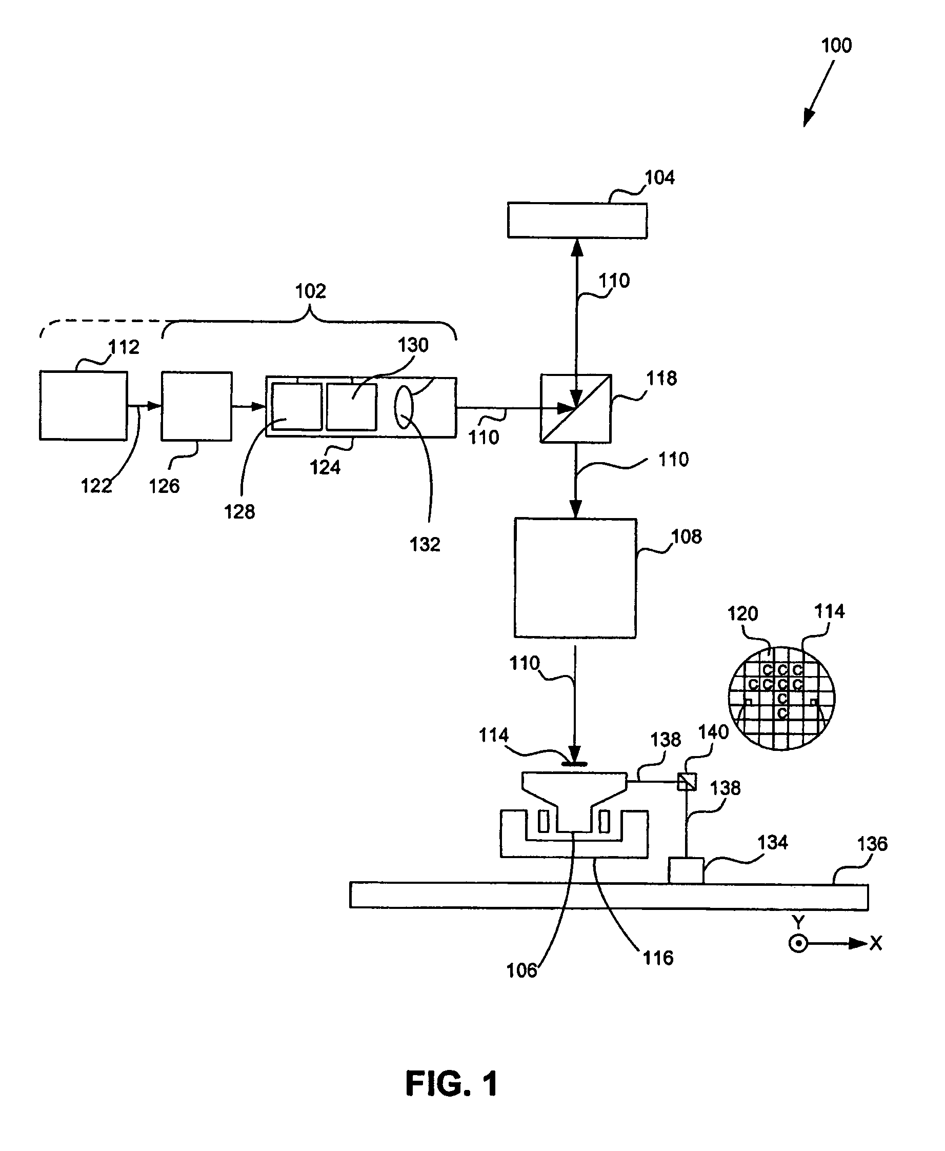
[0034]The term “array of individually controllable elements” as here employed should be broadly interpreted as referring to any means that can be used to endow an incoming radiation beam with a patterned cross-section, so that a desired pattern can be created in a target portion of the substrate. The terms “light valve” and “Spatial Light Modulator” (SLM) can also be used in this context. Examples of such patterning means may include the following.

[0035]A programmable mirror array. This may comprise a matrix-addressable surface having a viscoelastic control layer and a reflective surface. The basic principle behind such an apparatus is that, for example, addressed areas of the reflective surface reflect incident light as diffracted light, whereas unaddressed areas reflect incident light as undiffracted light. Using an appropriate spatial filter, the undiffracted light can be filtered out of the reflected beam, leaving only the diffracted light to reach the su...


PUM

PropertyMeasurementUnit
wavelengthaaaaaaaaaa

Abstract

An arrangement for adjusting the position on a substrate of a patterned beam generated by a light engine relative to the substrate. The arrangement moves an array of focusing elements, each of which focuses a portion of the patterned beam onto a point on the substrate, relative to an array of individually controllable elements to impart the pattern to the patterned beam.

Description

BACKGROUND OF THE INVENTION[0001]1. Field of the Invention[0002]The present invention relates to a lithographic apparatus and a device manufacturing method.[0003]2. Related Art[0004]A lithographic apparatus is a machine that applies a desired pattern onto a target portion of a substrate. Lithographic apparatus can be used, for example, in the manufacture of integrated circuits (ICs), flat panel displays and other devices involving fine structures. In a conventional lithographic apparatus, a patterning device, which is alternatively referred to as a mask or a reticle, may be used to generate a circuit pattern corresponding to an individual layer of the IC (or other device), and this pattern can be imaged onto a target portion (e.g., comprising part of, one or several dies) on a substrate (e.g., a silicon wafer or glass plate) that has a layer of radiation-sensitive material (e.g., photoresist or resist). Instead of a mask, the patterning device may comprise an array of individually c...

Claims


Application Information

Patent Timeline
Patent Type & Authority Patents(United States)
IPC IPC(8): G03B27/52G03B27/42G03B27/54G03F7/20H01L21/027
CPCG03F7/7025G03F7/70258G03F7/70275G03F7/7085G03F7/70791G03F7/70816G03F7/70825G03F7/70291B65G39/09B65G39/08B65G13/06F16C13/006
Inventor GUI, CHENG-QUNDE JAGER, PIETER WILLEM HERMAN
Owner ASML NETHERLANDS BV
Why Eureka
Try Eureka