
Medical image service method, medical software service method, medical image central management server apparatus, medical software central management server apparatus, medical image service system and medical software service system

a technology of medical software and service methods, applied in the field of medical software service methods, can solve the problems of user inability to remember all of their addresses, the device cannot perform well in a hospital, and the difficulty in accumulating and managing mr images over many years in the instrument having a small storage capacity, so as to reduce the processing speed

Inactive Publication Date: 2006-07-25
GE MEDICAL SYST GLOBAL TECH CO LLC
View PDF14 Cites 21 Cited by
  • Summary
  • Abstract
  • Description
  • Claims
  • Application Information

AI Technical Summary

Benefits of technology

[0014]It is therefore a first object of the present invention to provide a medical image service method and system which can alleviate the effect of restricted storage capacity in the storage of medical images, and which can deliver medical images to a multiplicity of parties via a network without need for the troublesome work of making contracts or conducting searches. It is also within this object to provide a server apparatus for this purpose.
[0015]A second object of the present invention is to provide a medical image service system which can reduce image processing load, and which can make a medical image subjected to image processing easily available.
[0016]A third object of the present invention is to provide a medical software service method and system which can reduce the work of managing medical software at the installation site of a medical image diagnosis apparatus, and which enables immediate utilization of the latest medical software at all times. It is also within this object to provide a server apparatus for this purpose.

Problems solved by technology

However, a local storage device often has a storage capacity intended only for minimum practical use in a common hospital because of restriction on cost or the like, and the device cannot perform well in a hospital which requires an especially large number of images taken or an especially long image storage period.
For example, assuming that three MRI apparatuses are installed in one hospital, and each MRI apparatus takes 1,000 images (=assuming the number of patients to be 20, and the number of images taken per patient to be 50) a day, the data size will be 128 megabytes a day and will be 37.5 gigabytes a year (assuming the number of operation days to be 300), which leads to difficulty in accumulating and managing MR images over many years in the instrument having a small storage capacity.
In other words, each party must make as many contracts as the number of partners it has, which is troublesome.
When the number of the partners is large, the user cannot remember all of their addresses.
The work of searching for a partner's address therefore takes place every time the address is needed, which is troublesome.
Moreover, when a medical image diagnosis apparatus performs image processing on a medical image, the following problems arise:
Furthermore, when medical software for medical image diagnosis apparatuses are separately managed in individual hospitals as in the past, the following problems occur:
(1) Each time new medical software is released, the hospitals must install it separately, which is time-consuming. Moreover, the work of software version management also falls on the hospital and is not an easy task.
(2) Since medical software can be updated only after the hospital obtains it as patch software recorded on a storage medium (such as an FD or MO), the time of the actual update is delayed relative to the release date. This is especially inconvenient when new hardware is introduced (for example, a new type of RF coil is installed in an MRI apparatus).

Method used


Image

  • Medical image service method, medical software service method, medical image central management server apparatus, medical software central management server apparatus, medical image service system and medical software service system
  • Medical image service method, medical software service method, medical image central management server apparatus, medical software central management server apparatus, medical image service system and medical software service system
  • Medical image service method, medical software service method, medical image central management server apparatus, medical software central management server apparatus, medical image service system and medical software service system

Examples


first embodiment

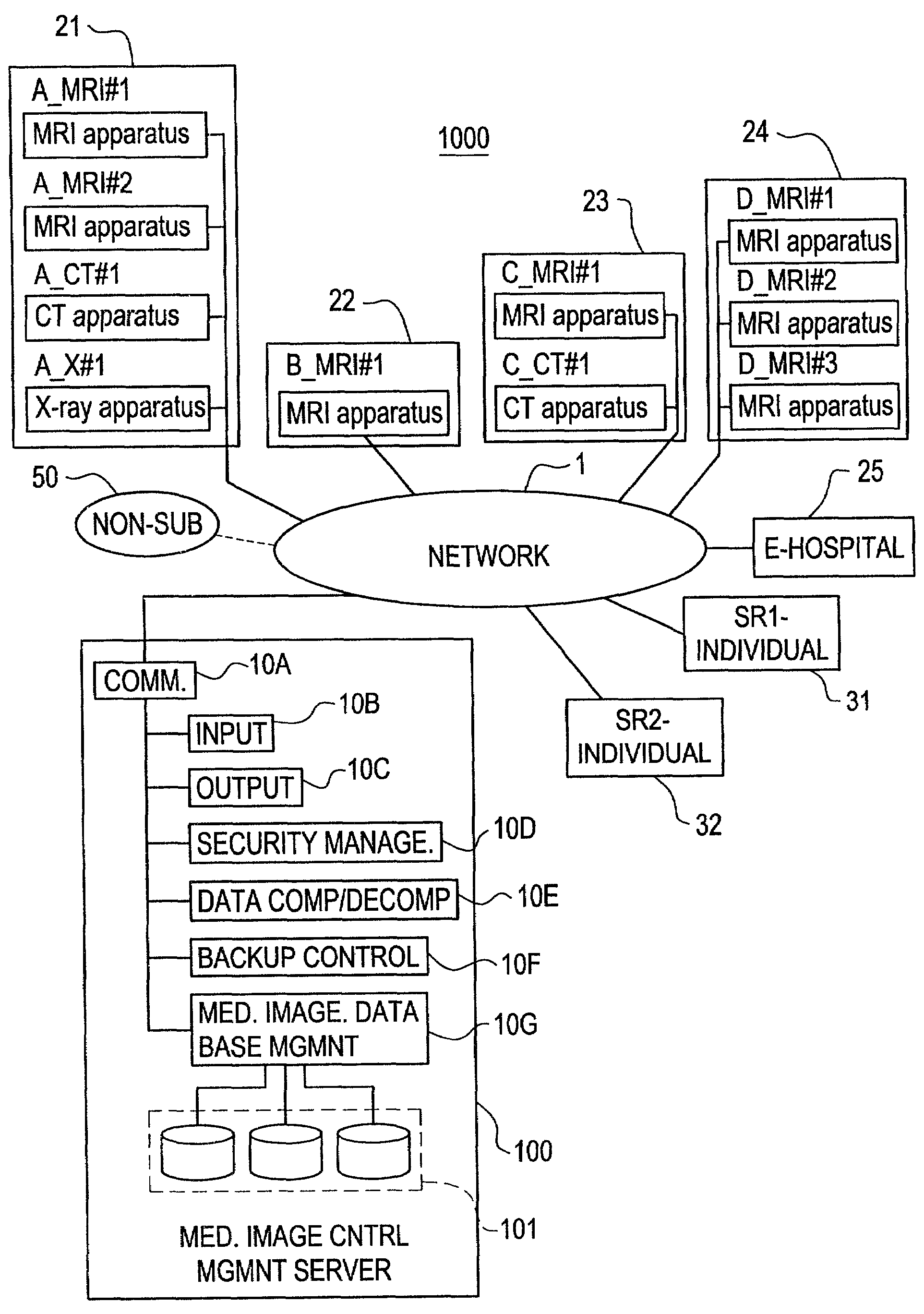
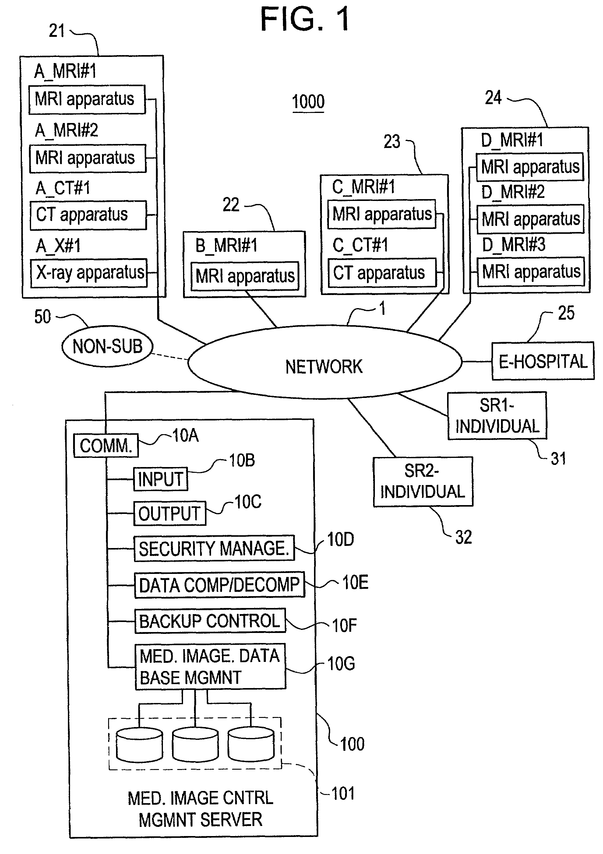
[0102]FIG. 1 is a block diagram showing a medical image service system 1000 in accordance with a first embodiment of the present invention.

[0103]The medical image service system 1000 comprises a network 1 such as the Internet, a LAN (local aria network) or a WAN (wide aria network), an A-hospital 21, B-hospital 22, C-hospital 23, D-hospital 24, E-hospital 25, and an SR1-individual 31 and SR2-individual 32, and a medical image central management server apparatus 100, all connected to the network 1. The communication medium for the network 1 may be wired, wireless or a combination thereof.

[0104]When the network 1 is the Internet, a non-subscriber 50 is also connected to the network 1. The non-subscriber 50 is a terminal that has not concluded a contract to use the medical image central management server apparatus 100.

[0105]In addition, it is preferred to use an SSL (secure socket layer protocol) or the like in the interest of security.

[0106]In the A-hospital 21, MRI apparatuses (A_MRI...

second embodiment

[0158]FIG. 6 is a block diagram showing a medical image service system 2000 in accordance with a second embodiment.

[0159]A terminal 211 of an image-receiving subscriber (assumed to be an A-hospital 21) sends to its associated hard copy device 212 format information defining the frame position, image size and the like of a medical image to be printed on a film. It should be noted that the format information contains image identifier information for identifying the medical image for each frame. The hard copy device 212 is, for example, a multi-format camera or a laser imager.

[0160]Upon receiving the format information, the hard copy device 212 sends a request for delivery of the medical image corresponding to the image identifier information to the medical image central management server apparatus 100 via the network, and receives the medical image. Then the hard copy device 212 prints the medical image in the area corresponding to the frame position and the image size.

[0161]According...

third embodiment

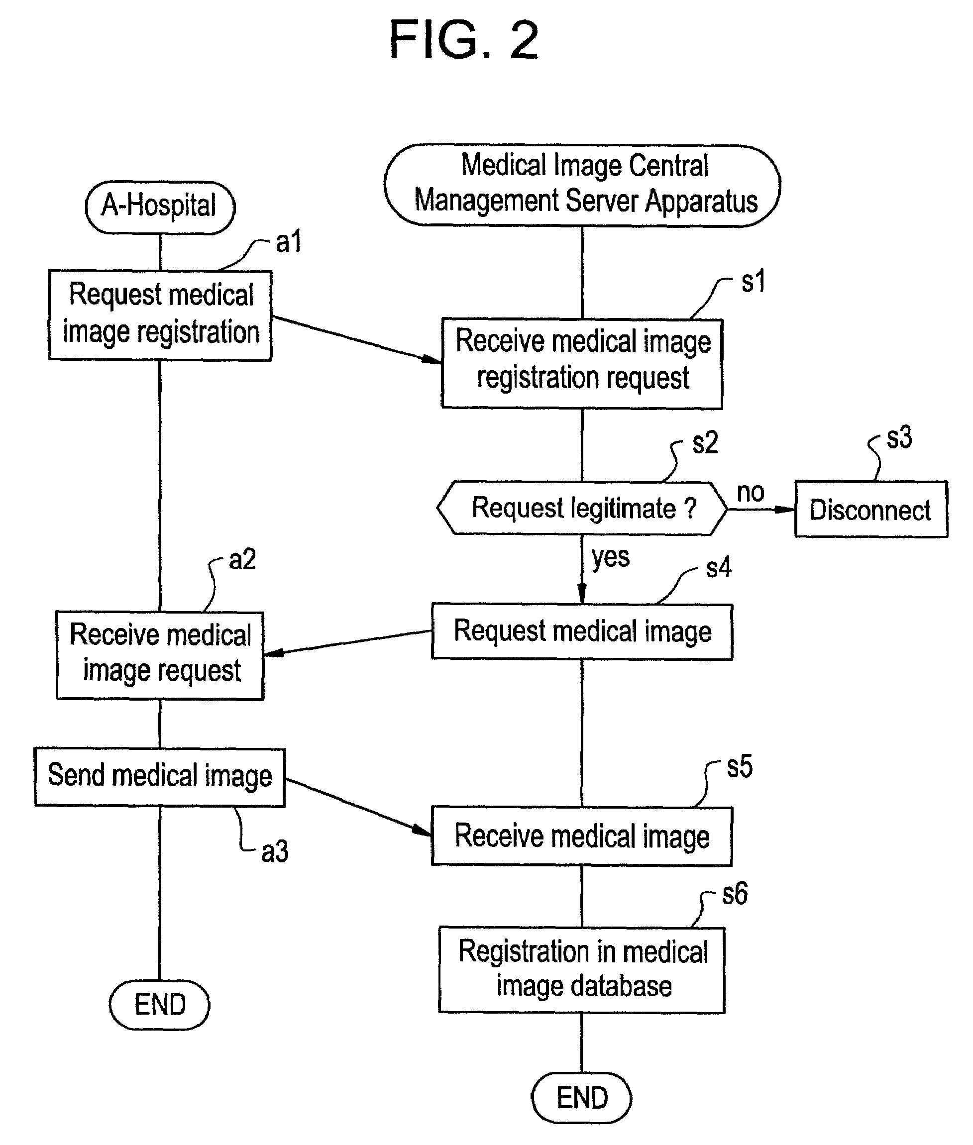
[0162]FIG. 7 is a flow chart showing processing for registering a medical image in a medical image service system in accordance with a third embodiment. The flow on the left is for the image-registering subscriber. The flow on the right is for the medical image central management server apparatus 200 (corresponding to 100 in FIG. 1).

[0163]Steps a1–a3 are the same as the processing described with reference to FIG. 2, and therefore the explanation thereof will be omitted.

[0164]Steps s1–s5 are the same as the processing described with reference to FIG. 2, and therefore the explanation thereof will be omitted.

[0165]In Step s55, the medical image central management server apparatus 200 sends a request for the imaging conditions of the medical image registered in the medical image database 101 to the A-hospital 21 via the network 1.

[0166]In Step a34, the A-hospital 21 receives the imaging condition request.

[0167]In Step a35, the A-hospital 21 sends the imaging conditions to the medical im...


PUM


Abstract

An image processing system having a server which applies image processing to a medical image sent by a subscriber via a generally available network, such as the “internet”, and sends the results of the image processing back to that subscriber or to another subscriber as instructed upon verification of the legitimacy of the instructions. In this manner, the processing load is reduced and medical images are made more readily and easily accessible.

Description

BACKGROUND OF THE INVENTION[0001]The present invention relates to a medical image service method, medical software service method, medical image central management server apparatus, medical software central management server apparatus, medical image service system and medical software service system. More particularly, the present invention relates to a medical image service method, medical software service method, medical image central management server apparatus and medical software central management server apparatus which can reduce the work of managing medical images and medical software, relative to individual management thereof, at the installation site of a medical image diagnosis apparatus, and a medical image service system and medical software service system which can reduce the work of management and image processing relative to individual management and image processing.[0002]In general, medical images taken at a hospital are accumulated in a local storage device in the...

Claims


Application Information

Patent Timeline
Patent Type & Authority Patents(United States)
IPC IPC(8): G06F17/30A61B5/00G06F15/173G06Q10/00A61B5/055G06T1/00G16H10/60
CPCG06F19/321G06F19/3418G06Q50/22G06Q50/24Y10S707/99948Y10S707/99943Y10S707/99945G16H30/40G16H30/20G16H40/67G16H80/00
Inventor OGINO, TETSUOSHIRAISHI, TOSHIHITOTSUNODA, TOSHIO
Owner GE MEDICAL SYST GLOBAL TECH CO LLC
Learn More