Normally white, supertwist nematic liquid crystal display of reflective type

a liquid crystal display and supertwist technology, applied in liquid crystal compositions, instruments, chemistry apparatuses and processes, etc., can solve the problems of unknown optimum direction of optical transmission axis of the polarizer, prohibit the display from being used in applications that require high resolution, etc., to achieve large display thickness, large light transmission loss, and complex design

Inactive Publication Date: 2006-08-01
NITTO DENKO CORP
View PDF22 Cites 11 Cited by
  • Summary
  • Abstract
  • Description
  • Claims
  • Application Information

AI Technical Summary

Benefits of technology

[0018]Accordingly, one of the objectives of the present invention is to overcome the aforementioned drawbacks of known STN displays such as large losses of light transmission upon passing through the multilayer structure of the display, complexity of design, large display thickness, low contrast ratio and multiplexing ability, and low brightness.

Problems solved by technology

One of the drawbacks of this known STN display is that the optimum direction of the optical transmission axis of the polarizer, which provides maximum contrast of the display, is not known.
The drawback of this design is image parallax, which prohibits the display from being used in applications that require high resolution.
Since a second polarizer is necessary, the design cannot be simplified by combining the functions of a mirror and an electrode in a single element.
The drawback of this design is that it is impossible to precisely transform elliptical polarization into linear polarization for all wavelengths at any selected operating voltage across the liquid crystal.
This drawback manifests itself in relatively low image contrast.
Another drawback of this design is the inclusion of the compensator, which complicates the design of the display.
First, either distortions of color rendition are possible, or using different voltage for the blue, red or green colors may result in a more complex design of display.
Second, since the phase compensator and the liquid crystal have to have weak dispersion, optical parameters of which are interrelated, material selection for the design is hindered.
The drawback of above mentioned displays using a phase compensator plate is that the image is very sensitive to the thickness of the liquid crystal and the phase compensator, i.e., sensitive to the precision of fabrication.
Besides, correction of image distortions related to fabrication tolerances complicates the design and imposes special requirements to the properties of the liquid crystal.
The drawback of this design is the uncertainty of the mentioned parameters, which complicates the optimization.
One of the drawbacks of the display is, first, the high sensitivity to a voltage level of a switched off condition, i.e., the voltage which defines transmission state of the display.
It also does not maintain the achromaticity when it transits from the “black” state to the “white” state.
Moreover, the level of contrast and brightness is insufficient.
The drawback of this display is, first, the wide range of optical path differences proposed by the authors.
This display suffers from poor stability within the region of the suggested angles.
In other words, the proposed solution does not take into account the high sensitivity of the mixed regime of operation of the liquid crystal to the precision of fabrication of displays.
Another drawback is the non-standard values of the twist angles.
The small values of twist angles do not provide multiplexing ability of the display.
The drawback of this display is that the display contains a retarder layer, and that the optimum orientations of the optical transmission axis of the polarizer which provide the maximum contrast of the display are not known.
The presence of the retarder in the display results in additional losses of light transmission, complicates the design of the display, increases its size, and raises the manufacturing cost of the display.
Despite the author's claims of generalized displays with a single polarizer, these displays are not truly single polarizer displays.
The use of the retarder complicates the design and makes additional problems when internal polarizers made of a thin crystalline film (TCF) are used.
Another disadvantage is the fact that the author assumes the “black” state (or “bright” state for normally-black mode) corresponding to the homeotropic distribution of the LC director.
It is not the case for STN designs, where to obtain high multiplexing ability the black state does not correspond to the truly homeotropic distribution of the LC director, because it may lead to high voltage difference between OFF and ON states, which is incompatible with a high multiplexing level.

Method used


Image

  • Normally white, supertwist nematic liquid crystal display of reflective type
  • Normally white, supertwist nematic liquid crystal display of reflective type
  • Normally white, supertwist nematic liquid crystal display of reflective type

Examples


Embodiment Construction

[0043]As used herein, the term “front” when used to describe glass layer, electrode, protective layer, polarizer, alignment layer, transmission axes and alignment directions means that the described element is located on the viewer side of the chiral nematic liquid crystal (CNLC) and faced to a light source.

[0044]As used herein, the term “rear” when used to describe glass layer, electrode, protective layer, alignment layer, transmission axes and alignment directions means that the described element is located on side of the liquid crystal opposite to the viewer and faced to a reflector.

[0045]Under Liquid Crystal Display (LCD) here and below we understand either a liquid crystal display or its part in the device.

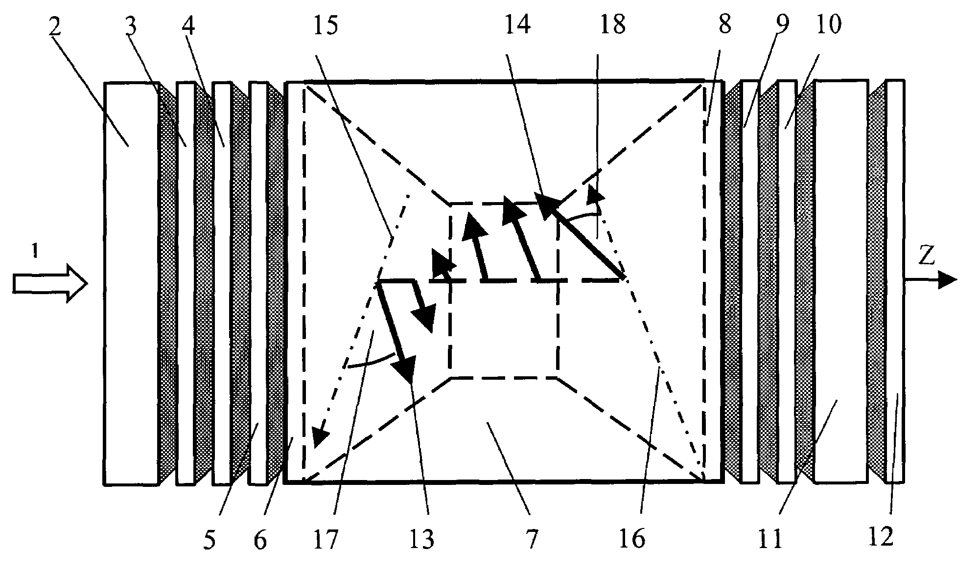
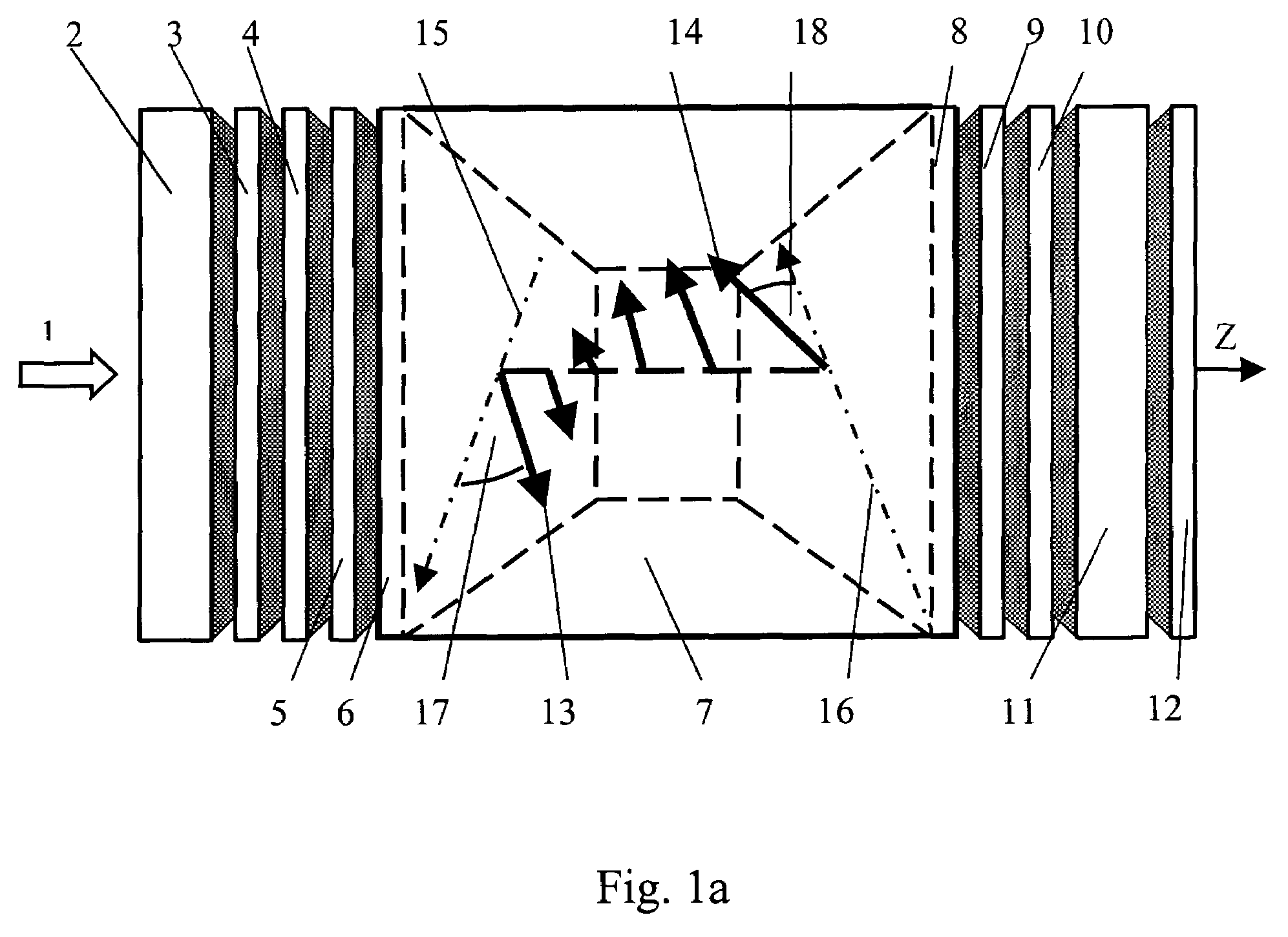
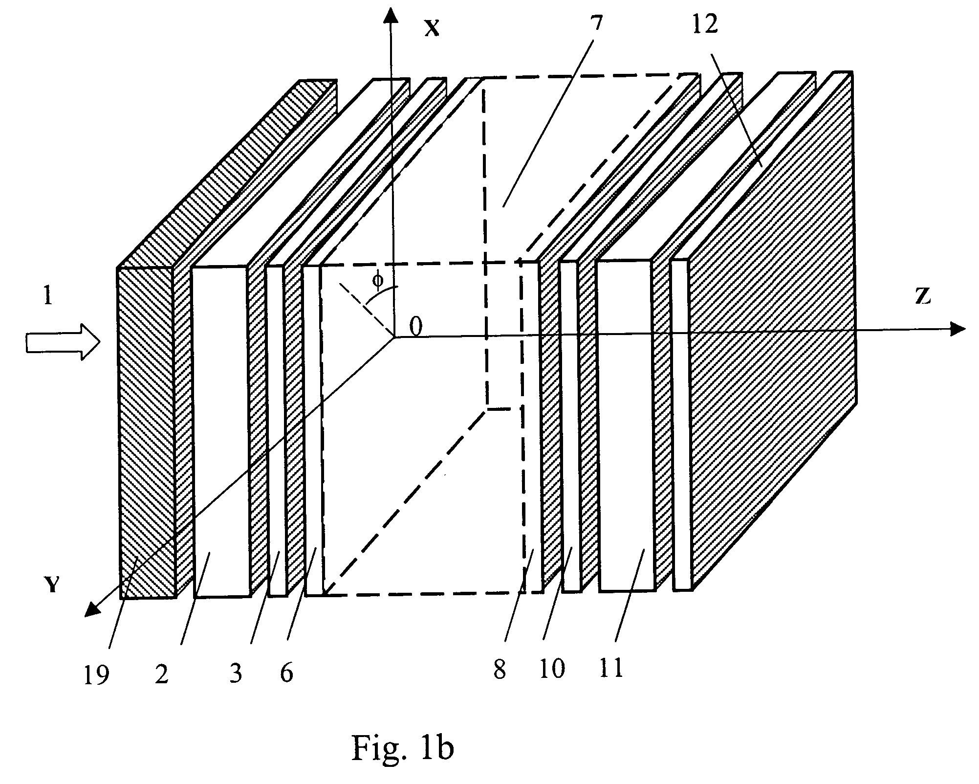
[0046]As shown in FIG. 1a, an embodiment of this invention comprises a light source 1, a front glass plate 2, a front optically transparent electrode 3, a front optically transparent protective layer 4, front polarizer 5, a front alignment PI-layers 6, a chiral nematic liquid...


PUM

PropertyMeasurementUnit
twist angleaaaaaaaaaa
twist anglesaaaaaaaaaa
twist angleaaaaaaaaaa

Abstract

A normally white supertwist nematic liquid crystal display of reflective type is provided. This display comprises a reflector, a layer of chiral nematic liquid crystal having a front aligning surface facing a light source and a rear aligning surface facing the reflector, and a front polarizer. The nematic liquid crystal has an optical retardation (Δnd) of the layer and a distribution of directors, wherein the chiral nematic liquid crystal has a twist angle (Φ) between an alignment direction of the director at the front aligning surface and an alignment direction of the director at the rear aligning surface. The front polarizer is disposed between the layer of chiral nematic liquid crystal and the light source. The front polarizer has a transmission axis forming an angle (α) with the alignment direction of the director at the front aligning surface of the chiral nematic liquid crystal layer. The optical retardation (Δnd) and the angle (α) are defined by the following formulas:α((Φ)=sign(Φ)·(47.0−0.4936|Φ|+2.6786×10⁻³·Φ2)±5, deg, andΔnd(Φ)=−11.674+0.1915·|Φ|−9.8393×10⁻⁴·Φ21.6667×10⁻⁶·|Φ|3±0.05, μm.

Description

CROSS-REFERENCES TO RELATED APPLICATIONS[0001]This application is a continuation-in-part of U.S. patent application Ser. No. 10 / 272,833, filed Oct. 16, 2002, now abandoned the entire disclosure of which is hereby incorporated by reference.BACKGROUND[0002]The present invention relates in general to liquid crystal displays (LCDs), and in particular to normally white, supertwist nematic liquid crystal displays of reflective type.[0003]Reflective liquid crystal displays are widely used in mobile systems, since they feature very low energy consumption, small size, low weight, and are convenient for use outdoors. Reflective displays with a single polarizer have good potential for reaching high brightness, enhanced contrast ratio and low energy consumption.[0004]Supertwist nematic liquid crystal displays (STN displays) of reflective type with single polarizer possess potentially high brightness and good color rendition capacity. STN displays are characterized by large twist angles of nemat...

Claims


Application Information

Patent Timeline
Patent Type & Authority Patents(United States)
IPC IPC(8): G02F1/1335C09K19/02G02F1/139
CPCC09K19/0208G02F1/1397G02F2203/66G02F2203/02
Inventor PAUKSHTO, MICHAEL V.PALTO, SERGUEI
Owner NITTO DENKO CORP
Why Eureka
Try Eureka