
Power supply apparatus and power supply method

a power supply apparatus and power supply technology, applied in the direction of dc motor rotation control, feed-through capacitors, engine starters, etc., can solve the problems of short service time device bulkiness, and short service life of batteries for delivering such high currents, etc., to achieve high charge and discharge efficiency, long life, and high power density of supercapacitors

Active Publication Date: 2006-08-01
POWER REGENERATION
View PDF21 Cites 58 Cited by
  • Summary
  • Abstract
  • Description
  • Claims
  • Application Information

AI Technical Summary

Benefits of technology

"The present invention provides a power supply method and apparatus using the unique properties of symmetric capacitors to improve the performance of hybrid power sources consisting of batteries and supercapacitors. By reversing the polarity of the electrodes of the supercapacitor repeatedly in the charging-discharging cycles, the method improves the energy-utilization efficiency of the batteries and stabilizes the output voltages of the capacitors during discharging. The power supply apparatus includes a voltage source, at least one capacitor connected with the voltage source in series, and at least one switching mechanism capable of reversing the polarity connection between the voltage source and the capacitor. The method and apparatus can be used in various power supply applications, such as powering a load using a combination of a supercapacitor and a battery."

Problems solved by technology

Though lead acid batteries are well known by high power densities as they are commonly used to start automobiles, the batteries have short service time for delivering such high currents.
In return, the use time and lifetime of the batteries are compromised, and the devices tend to be bulky if they are made to work long.
Such switching of polarity connection is not permitted for batteries or conventional capacitors for the polarity of their electrodes are fixed.
If the electrodes of the latter are misconnected, some catastrophe, for example, explosion, may happen.
Supercapacitors can only store energy but cannot generate energy.
Actually, the two defects are all related to the low energy content of supercapacitors.
However, the voltages of the supercapacitors fall rapidly at discharging.
On the other hand, in many household products driven by disposable or primary alkaline batteries, the end of the battery life does not mean a complete drainage of the energy content of the batteries.
Therefore, a lot of energy is wasted every time when an alkaline battery is claimed dead.

Method used


Image

  • Power supply apparatus and power supply method
  • Power supply apparatus and power supply method
  • Power supply apparatus and power supply method

Examples


first embodiment

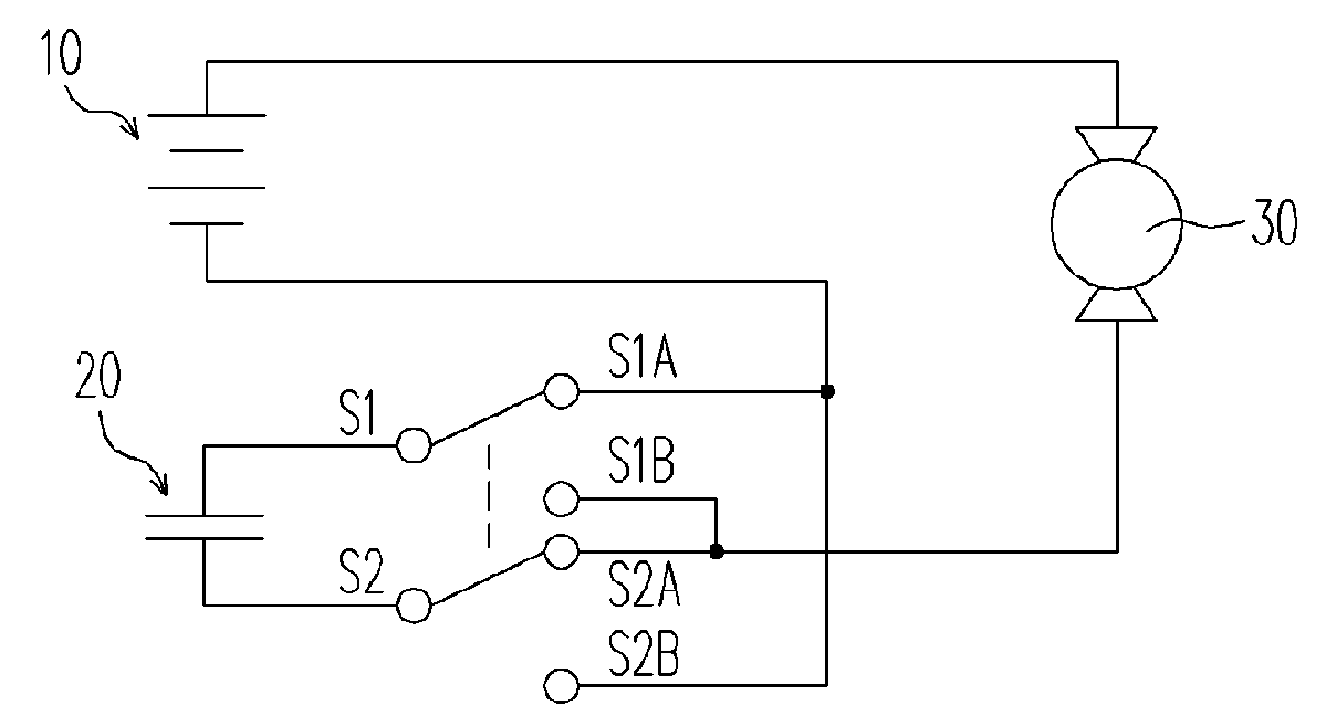
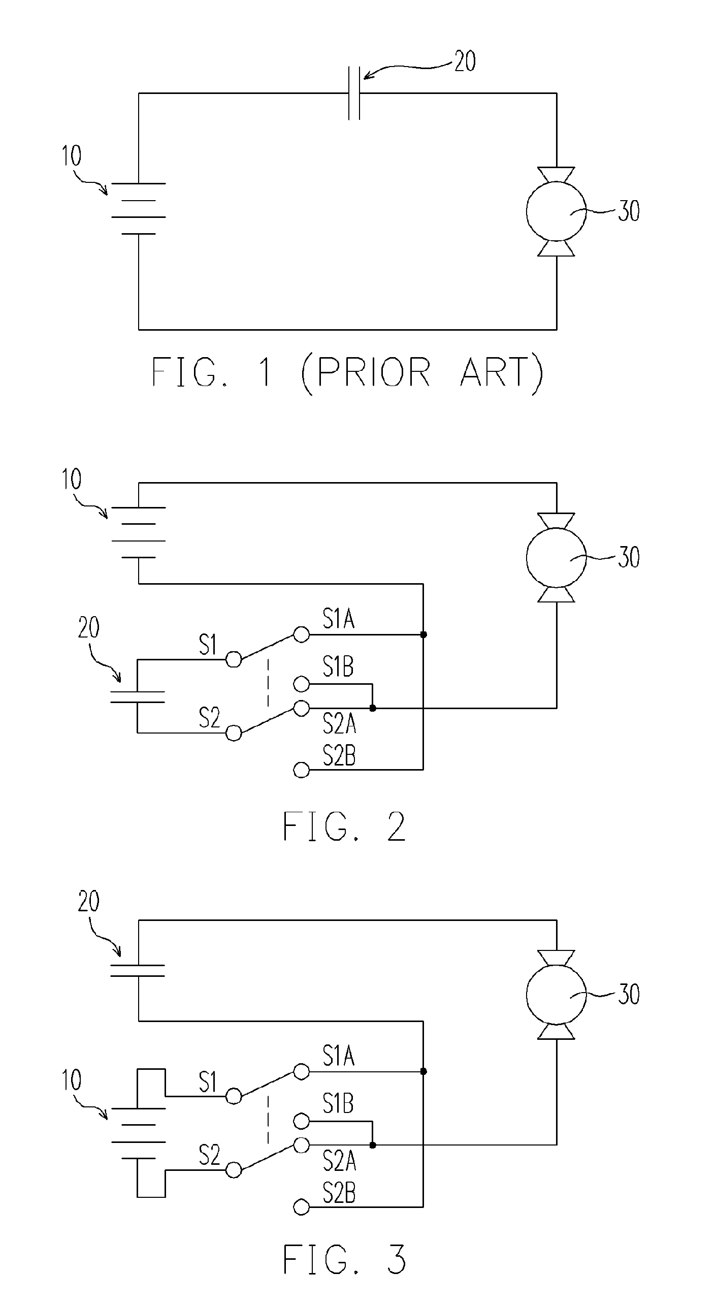
[0033]FIG. 2 illustrates the first embodiment of this invention wherein the polarity connection of the supercapacitor 20 to the battery 10 is controlled by a double-pole, double-throw (DPDT) controller consisting of two switches. With DPDT at the state of S1–S1A and S2–S2A as shown in FIG. 2, the supercapacitor 20 will be charged by the battery 10 at the same time while the load 30 is driven by the battery 10. Even under the situation that the voltage of the battery 10 is insufficient to drive the load 30, a charging current can still pass the load 30 to charge the supercapacitor 20. The flow path of charging current is as follows: the positive pole (longer bar) of the battery 10, the load 30, S2A, S2, the supercapacitor 20, S1, S1A, and then the negative pole (shorter bar) of the battery 10. As soon as the supercapacitor 20 is charged to the potential of the battery 10, the charging current stops flowing and the load 30 will be stalled.

[0034]Subsequently, by switching the DPDT to t...

second embodiment

[0042]FIG. 3 shows the second embodiment of the present invention on using the reciprocating switches for a load 30 moving bi-directionally, for example, a garage door, an electric curtain or an elevator. With the DPDT is set at the state as shown in FIG. 3, the battery 10 provides a current that flows as follows: the positive pole (longer bar) of the battery 10, S1, S1A, the supercapacitor 20, the load 30, S2A, S2 and the negative pole (shorter bar) of the battery 10. The current may drive the load 30, but will definitely charge the supercapacitor 20 so long as the supercapacitor 20 has a lower potential than the battery 10. When the supercapacitor 20 is charged to the negative potential of the battery 10, the current flow will cease and the load 30 will be stalled.

[0043]Alternatively, the discharging of the battery 10 can be synchronized with the movements of the load 30, that is, the battery 10 terminates discharging when the load 30 stops. In the case that the driving force of t...

third embodiment

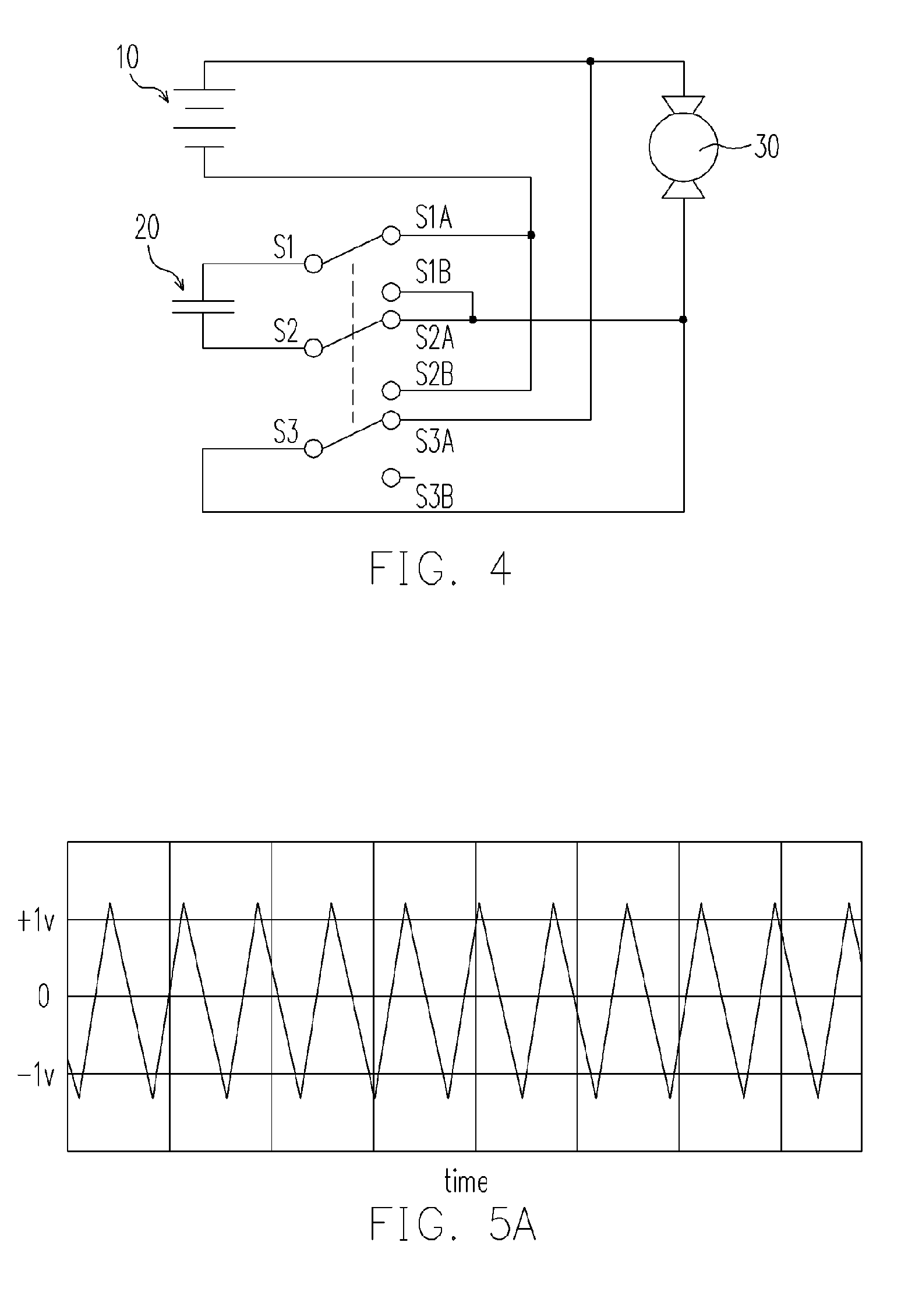
[0046]FIG. 4 shows the third embodiment of the present invention wherein the battery 10 quickly charges the supercapacitor 20 without passing the load 30. A trigger with three pole double throw (TPDT) consisting of three switches, wherein S1, S2 and S3 are common contacts, is employed for reversing the polarity connection between the supercapacitor 20 and the battery 10. As the TPDT is at the normally closed state (S1–S1A, S2–S2A and S3–S3A) as shown in FIG. 4, the battery 10 will charge the supercapacitor 20 by the following route: the positive pole (longer bar) of the battery 10, S3A, S3, S2A, S2, the supercapacitor 20, S1, S1A and the negative pole (shorter bar) of the battery 10. A push-latching button (not shown) can be used to initiate the charging of the supercapacitor 20.

[0047]Since the charging current does not flow through the load 30, the load 30 is stationary. Moreover, as the battery 10 and the supercapacitor 20 are essentially in an electric-short state, the battery 10...


PUM


Abstract

A power supply apparatus and a power supply method are described, wherein the non-polar characteristics of the electrodes of a capacitor is utilized to improve the energy utilization efficiency of a battery through reciprocating switches of polarity connection between the battery and the capacitor. The voltages of the capacitors can also stay at a near constant level using the polarity reversal mechanism.

Description

BACKGROUND OF THE INVENTION[0001]1. Field of the Invention[0002]The present invention relates to power supply equipment. More specifically, the invention relates to a power supply apparatus and a power supply method that use a battery and a capacitor to deliver a stable power output. The power supply apparatus and method are capable of saving energy via reciprocal switches of the polarity connection between the battery and the capacitor.[0003]2. Description of the Related Art[0004]Batteries have become a necessity in modern life, and are used daily in various areas from automobiles to consumer products such as cell phones, laptops and music players. Batteries depend on chemical reactions for energy conversion at charging and discharging, and are normally designed for applications using low powers. Because the chemical reactions of batteries require overcoming some energy barriers, batteries are prevented from fast charging and discharging. Though lead acid batteries are well known b...

Claims


Application Information

Patent Timeline
Patent Type & Authority Patents(United States)
IPC IPC(8): H01G4/00H01G9/058
CPCF02P3/0442H02P7/28H02J7/345H02P7/0044H01M10/4264F02N11/0866H02P7/04Y02E60/10
Inventor SHIUE, LIH-RENCHUNG, HSING-CHEN
Owner POWER REGENERATION
Learn More