
Device and method for monitoring respiration

Inactive Publication Date: 2006-08-08
PAGE THOMAS C
View PDF17 Cites 33 Cited by
  • Summary
  • Abstract
  • Description
  • Claims
  • Application Information

AI Technical Summary

Benefits of technology

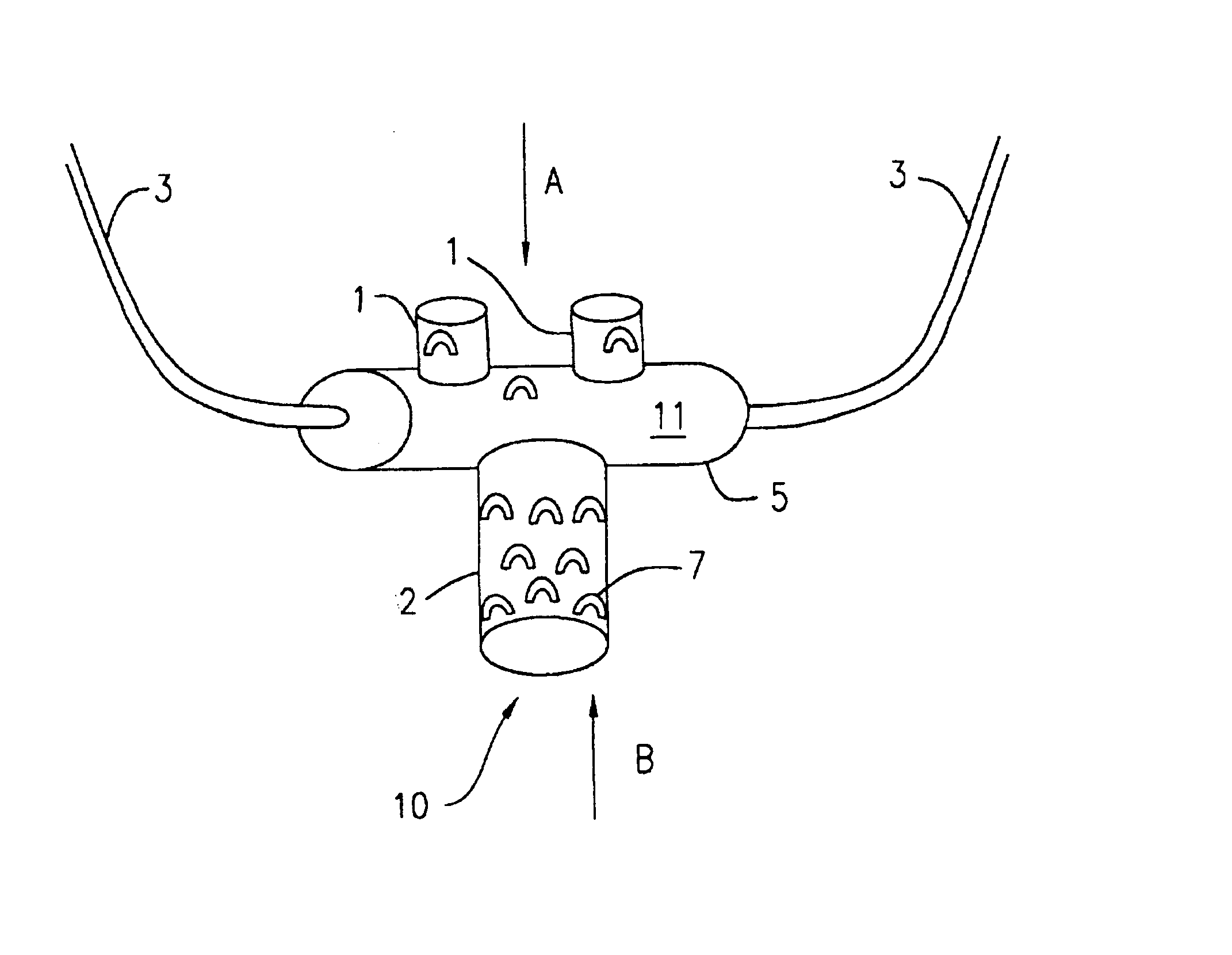
[0009]The present invention overcomes the disadvantages found in the prior art by providing a plurality of respiration related signals, derived from different physical phenomena, from a single sensor element fabricated on a single substrate. Moreover, the present invention includes a sensor construction which is less susceptible to interference from the external environment and loss of signal. It is advantageous to monitor multiple sensing channels, provided that care is taken to increase reliability of each channel, so that the overall reliability of the monitoring system is enhanced. In the present invention, all these advantages are achieved by employing a “closed volume / corrugated surface” (CVCS) respiration flow probe, rather then the “open tube” cannula type or the various thermo-sensor approaches described in the Background section above.
[0012]Preferably, corrugations or undulations are disposed on the outside surface, so that when the patient breathes over the sensor, the corrugations increase turbulence of the respiratory airflow over the outer surface to thereby increase the level of sound generated by respiration, allowing for better and more accurate detection. The inflatable body preferably includes a bendable inelastic substrate and a plastic inflatable film sealingly attached to the substrate to form the interior volume. A proximal surface of the sensor is disposable against the face of the patient between the nose and mouth. A hole is preferably formed in the proximal surface communicating with the interior volume, so that when the sensor is disposed on the patient's face, the hole is covered and closed by the patient's face. If the sensor loses contact with the patient's face, the hole opens, and the interior volume is in communication with the ambient air; the monitor detects the concomitant change in pressure of the interior volume.

Problems solved by technology

All of the above methods are complicated and expensive, or else unworkable in a real hospital setting for perioperative patients.
However, a pulse oximeter can only detect hypoxia after the condition has arisen, i.e., after respiratory depression has occurred for a significant period of time.
Other possible solutions (and their associated problems) include capnographic end tidal CO2 monitors (highly accurate but prohibitively expensive), hemodynamic monitors which use Swan Ganz pulmonary artery catheters (expensive and have a high morbidity), and increased physician- or nurse-to-patient ratios (prohibitively expensive and inefficient).

Method used


Image

  • Device and method for monitoring respiration
  • Device and method for monitoring respiration
  • Device and method for monitoring respiration

Examples


Embodiment Construction

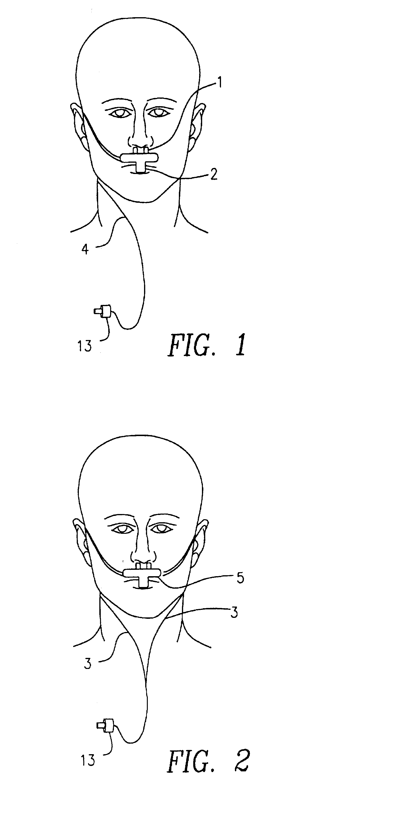
[0027]The preferred embodiment of the respiratory sensor is fabricated using lamination and adhesive techniques on a film substrate. The lamination is performed in such a way as to provide the proper physical relationship of the individual sensor parts, which detects the patient's nasal and oral respiration. The sensor is a closed volume or bubble of plastic film with extensions or protrusions extending towards the nostrils and mouth.

[0028]Respiration is detected through the change in temperature of the air enclosed in this bubble when ambient room air, inspiratory, and expiratory air flows pass over the sensor. This change in temperature generates a change in pressure in the closed volume largely in accordance with Gay-Lussac's Law, which is:

P / T=P′ / T′ where V is constant  (1)

and where P=pressure, T=temperature, V=volume.

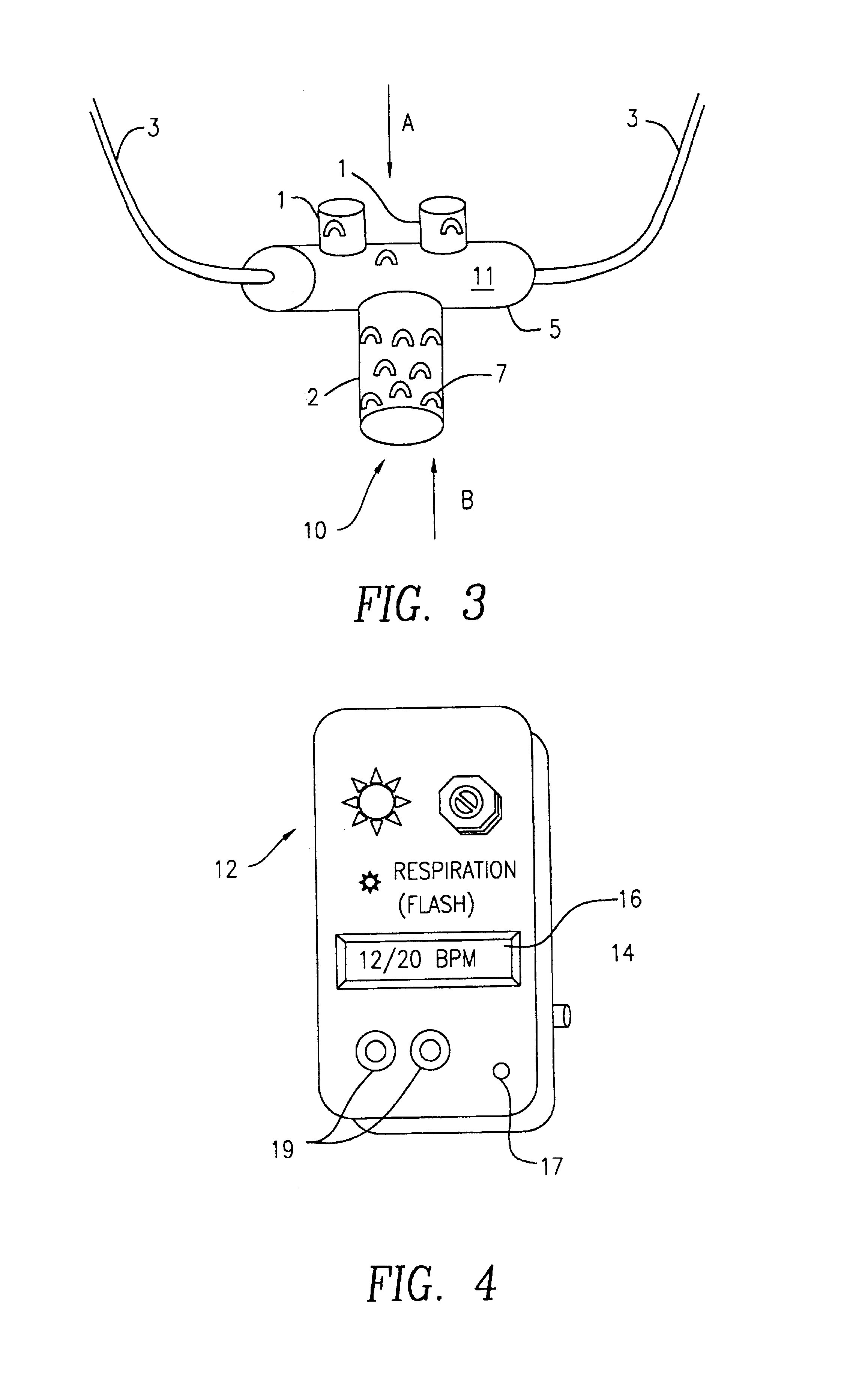
These pressure changes are monitored by a pressure sensor in the control box connected to the bubble via at least one tube.

[0029]A second respiration input signal i...


PUM


Abstract

A system and method are provided to monitor a patient's respiration during and after medical / surgical procedures, as well as in clinical situations wherein the patient is at increased risk for developing central or obstructive respiratory depression and / or apnea. A sensor attached to the patient's face, which monitors nasal and oral air-flows. An electronic monitor analyzes patient respiratory patterns and initiates bedside and / or remote nursing station alarms in real time if and when a clinically significant respiratory event is detected. Respiration is measured by monitoring changes in the acoustic signature of the patient's breath passing over a corrugated or uneven surface, changes in the pressure of an inflatable closed volume of a sensor caused by the changes in temperature of the interior volume caused by the patient breathing over the sensor, or both.

Description

BACKGROUND OF INVENTION[0001]1. Field of Invention[0002]The present invention generally relates to respiratory sensor and alarm technology, and more particularly, relates to a dual mode respiratory airflow sensor and monitoring technology for the detection of any and all potentially life threatening respiratory events.[0003]2. Description of Related Art[0004]It is known in the art to monitor patients susceptible to disorders of the respiratory system, or in critical care settings, to employ respiration sensors and alarm systems. U.S. Pat. No. 4,878,502 issued to Dietz discusses a respiration airflow sensor employing a tube in which a ball is free to move, thereby breaking a beam of light. The ball is forced to move by the flow of air associated with the breathing of the patient. In U.S. Pat. No. 4,745,925 also issued to Dietz, another variation of an opthoelectric inhalation sensor using thin film deposition is discussed. Monitoring of respiration disorders by acoustic sensors is me...

Claims


Application Information

Patent Timeline
IPC IPC(8): A61B5/08A61B5/00A61B5/087A61B7/00
CPCA61B5/0816A61B7/003A61B5/0878
Inventor PAGE, THOMAS C.
Owner PAGE THOMAS C
Learn More