Magnetoresistive spin-valve sensor and magnetic storage apparatus

a technology of magnetoresistive spin-valve and magnetic storage apparatus, which is applied in the field of magnetoresistive spin-valve sensors and magnetic storage apparatuses, can solve the problems of difficult to decrease the thickness of the free layer and the thickness of the spacer layer,

Inactive Publication Date: 2006-08-08
FUJITSU LTD
View PDF6 Cites 8 Cited by
  • Summary
  • Abstract
  • Description
  • Claims
  • Application Information

AI Technical Summary

Benefits of technology

[0009]Accordingly, it is a general object of the present invention to provide a novel and useful magnetoresistive spin-valve sensor and magnetic storage apparatus in which the problems described above are eliminated.
[0010]Another and more specific object of the present invention is to provide a magnetoresistive spin-valve sensor and a magnetic storage apparatus, which can decrease the thickness of the magnetic layer and / or the spacer layer, while maintaining a small coercive field and a small interlayer coupling field Hin between a first magnetic (pinned) layer and a second magnetic (free) layer, so that an increased output can be obtained from the magnetoresistive spin-valve sensor.
[0011]Still another object of the present invention is to provide a magnetoresistive spin-valve sensor comprising a magnetic layer, a specular layer made of a metal oxide, a back layer, made of Au, Cu or an alloy thereof, interposed between the magnetic layer and the specular layer, and a metal layer disposed adjacent to the specular layer, opposite to the back layer, and made of a metal which improves GMR performance of the magnetoresistive spin-valve sensor. According to the magnetoresistive spin-valve sensor of the present invention, it is possible to decrease the thickness of the magnetic layer and / or a spacer layer, while maintaining a small coercive field and a small interlayer coupling field Hin between the magnetic layer and another magnetic layer, so that an increased output can be obtained from the magnetoresistive spin-valve sensor.
[0012]A further object of the present invention is to provide a magnetic storage apparatus for reading information from a magnetic recording medium, comprising a magnetoresistive spin-valve sensor which reads the information from the magnetic recording medium, where the magnetoresistive spin-valve sensor comprises a magnetic layer, a specular layer made of a metal oxide, a back layer made of Au, Cu, AuCu, AgCu, AuAgCu or an alloy thereof and interposed between the magnetic layer and the specular layer, and a metal layer disposed adjacent to the specular layer, opposite to the back layer, and made of a metal which improves GMR performance of the magnetoresistive spin-valve sensor. According to the magnetic storage apparatus of the present invention, it is possible to decrease the thickness of the magnetic layer and / or a spacer layer of the magnetoresistive spin-valve sensor, while maintaining a small coercive field and a small interlayer coupling field Hin between the magnetic layer and another magnetic layer, so that an increased output can be obtained from the magnetoresistive spin-valve sensor. As a result, it is possible to read information from a high-density magnetic recording medium.

Problems solved by technology

However, it is difficult to decrease the thickness of the free layer while maintaining a small coercive field and a small interlayer coupling field Hin between the pinned layer and the free layer, particularly when the specular layer is in direct contact with the free layer.
But it is difficult to decrease the thickness of the spacer layer without increasing the interlayer coupling field Hin between the pinned layer and the free layer.

Method used


Image

  • Magnetoresistive spin-valve sensor and magnetic storage apparatus
  • Magnetoresistive spin-valve sensor and magnetic storage apparatus
  • Magnetoresistive spin-valve sensor and magnetic storage apparatus

Examples


first embodiment

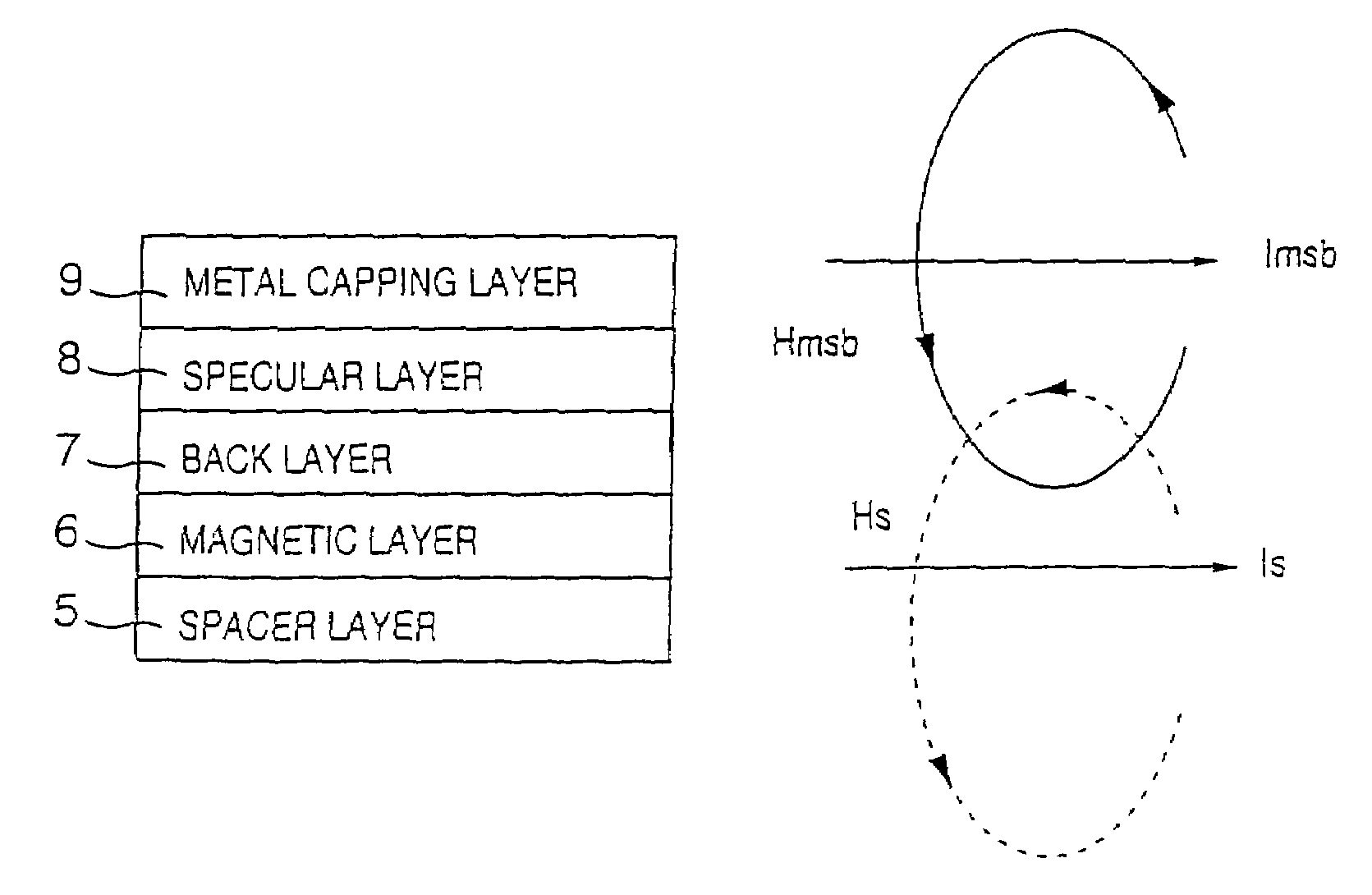
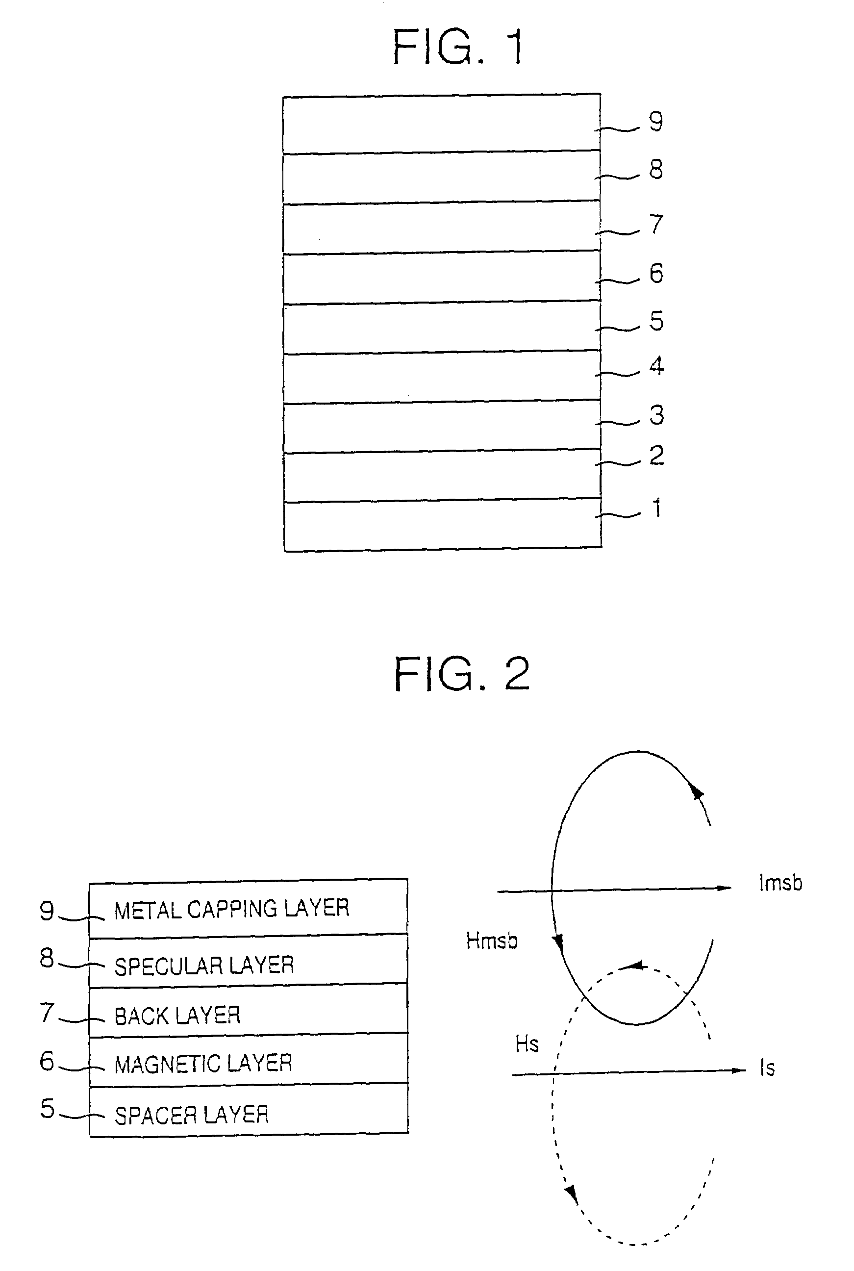
[0024]FIG. 1 is a cross sectional view showing the general structure of an important part of a magnetoresistive spin-valve sensor according to the present invention. The magnetoresistive spin-valve sensor shown in FIG. 1 generally includes a substrate 1, an underlayer 2, an antiferromagnetic layer 3, a first magnetic layer 4, a spacer layer 5, a second magnetic layer 6, a back layer 7, a specular layer 8, and a metal capping layer 9.

[0025]The first magnetic layer 4 is made of a magnetic material such as a Co-based alloy, and may have a single-layer structure or a multi-layer structure. The first magnetic layer 4 forms a pinned layer of the magnetoresistive spin-valve sensor. The spacer layer 5 is made of a nonmagnetic metal such as Cu. The second magnetic layer 6 is made of a soft magnetic material such as a Co-based alloy, and forms a free layer of the magnetoresistive spin-valve sensor. The second magnetic layer 6 may have a single-layer structure or a multi-layer structure. The b...

second embodiment

[0039]FIG. 7 is a cross sectional view showing the general structure of an important part of the magnetoresistive spin-valve sensor according to the present invention. In FIG. 7, those parts which are the same as those corresponding parts in FIG. 1 are designated by the same reference numerals, and a description thereof will be omitted.

[0040]In the first embodiment described above, the structure shown in FIG. 1 is provided at a top portion of the magnetoresistive spin-valve sensor. On the other hand, in this second embodiment, the structure shown in FIG. 7 is embedded inside the magnetoresistive spin-valve sensor. In this second embodiment, the magnetoresistive spin-valve sensor has an inverted structure as compared to that of the first embodiment, and the layers are disposed in a reverse order to that of the first embodiment.

third embodiment

[0041]FIG. 8 is a cross sectional view showing the general structure of an important part of the magnetoresistive spin-valve sensor according to the present invention. In FIG. 8, those parts which are the same as those corresponding parts in FIG. 1 are designated by the same reference numerals, and a description thereof will be omitted.

[0042]In the first embodiment described above, the structure shown in FIG. 1 is provided at a top portion of the magnetoresistive spin-valve sensor. On the other hand, in this third embodiment, the structure shown in FIG. 7 is embedded inside the magnetoresistive spin-valve sensor. In this third embodiment, the magnetoresistive spin-valve sensor has an inverted structure as compared to that of the first embodiment, and the layers are disposed in a reverse order to that of the first embodiment.

[0043]Furthermore, in this third embodiment, a metal underlayer 9-1 is provided under the specular layer 8. The metal underlayer 9-1 can provide the rest of the ...


PUM

PropertyMeasurementUnit
thicknessaaaaaaaaaa
thicknessaaaaaaaaaa
coercivityaaaaaaaaaa

Abstract

A magnetoresistive spin-valve sensor is constructed to include a magnetic layer, a specular layer made of a metal oxide, a back layer made of Au, Cu, AuCu, AgCu, AuAgCu or an alloy thereof and interposed between the magnetic layer and the specular layer, and a metal layer disposed adjacent to the specular layer, opposite to the back layer, and made of a metal which improves GMR performance of the magnetoresistive spin-valve sensor.

Description

[0001]This application, filed under 35 U.S.C. §111(a), is a continuation of International Application No. PCT / JP01 / 09447, filed Oct. 26, 2001, which claims priority from an International Application PCT / JP01 / 02261, filed Mar. 22, 2001.[0002]The International Application PCT / JP01 / 09447 was published in the English language under International Publication Number WO 20 / 078021 A1 on Oct. 3, 2003. The International Application PCT / JP01 / 02261 was also published in the English language under International Publication Number WO 02 / 077657 A1 on Oct. 3, 2003.TECHNICAL FIELD[0003]The present invention generally relates to magnetoresistive spin-valve sensors and magnetic storage apparatuses, and more particularly to a magnetoresistive spin-valve sensor having a specular layer, and to a magnetic storage apparatus which uses such a magnetoresistive spin-valve sensor.BACKGROUND ART[0004]A typical magnetoresistive spin-valve sensor includes a base layer, a first magnetic (pinned) layer, a spacer la...

Claims


Application Information

Patent Timeline
Patent Type & Authority Patents(United States)
IPC IPC(8): G11B5/127B32B9/00G01R33/09G11B5/33G11B5/39H01F10/30H01F10/32
CPCB82Y10/00B82Y25/00G01R33/093G11B5/39G11B5/3903H01F10/324Y10T428/1121H01F41/325Y10T428/1164Y10T428/1193G11B2005/3996G01R33/09
Inventor HONG, JONGILLKANAI, HITOSHIKANE, JUNICHINOMA, KENJI
Owner FUJITSU LTD
Why Eureka
Try Eureka