

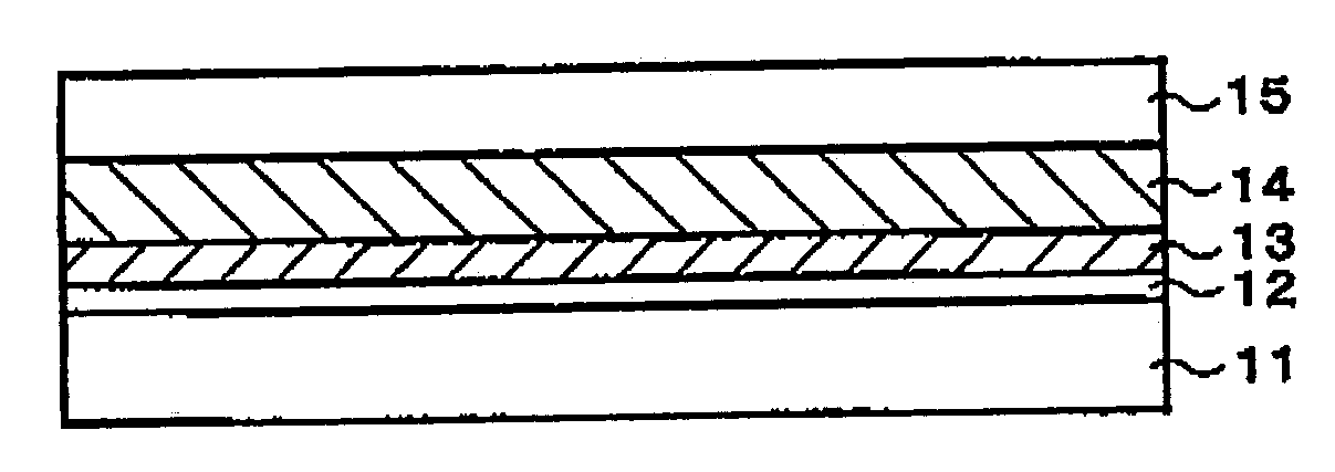
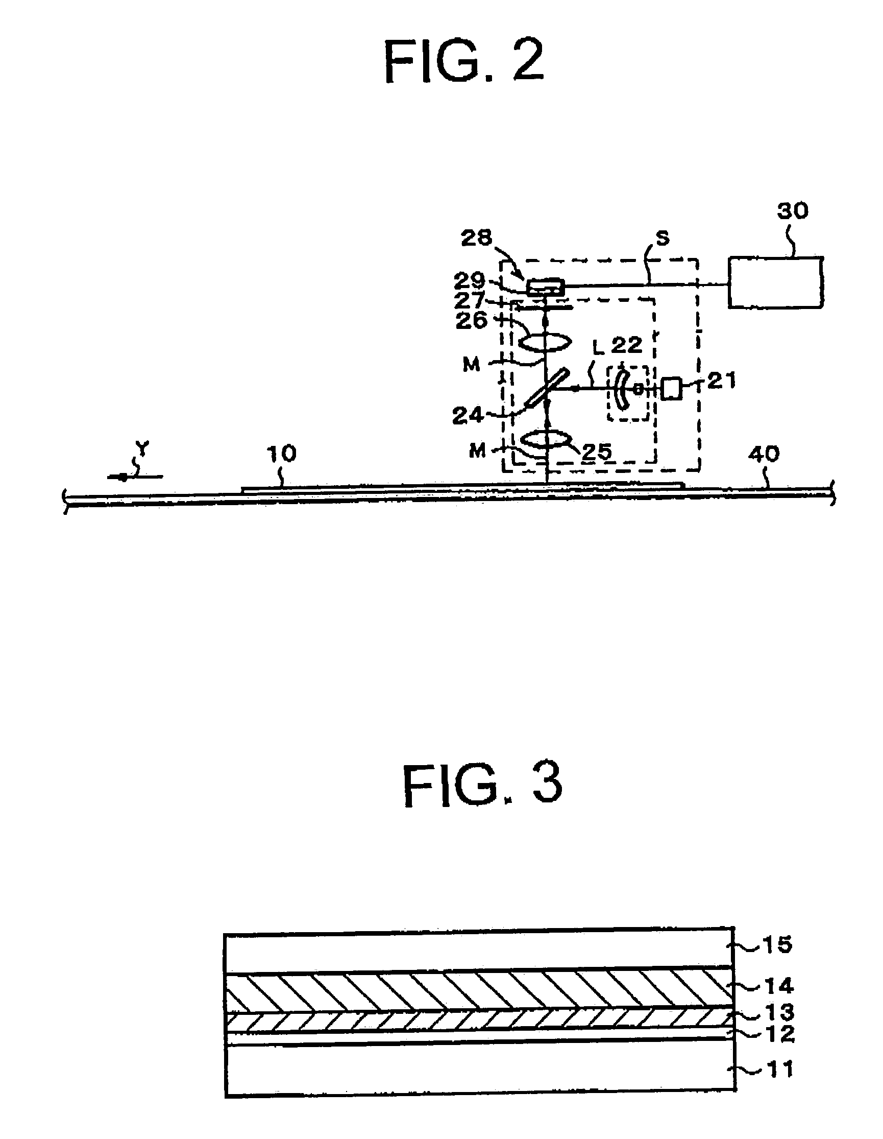
Radiation image storage panel
a radiation image and storage panel technology, applied in the field of radiation image storage panel, can solve the problems of impaired sharpness of a radiation image reproduced, and achieve the effect of high sensitivity and high sharpness
- Summary
- Abstract
- Description
- Claims
- Application Information
AI Technical Summary
Benefits of technology
Problems solved by technology
Method used
Image

Examples
example 1
(1) Preparation of Phosphor Sheet
[0114]
Tetradecahedral stimulable phosphor particles:1,000 gBaF (Br0.85I0.15): Eu (mean particlediameter (Dm): 5 μm)Binder: polyurethane elastomer 182 g(Pandex T-5265H: MEK solution of solidcontent 13 wt. %, Dai-nippon Ink &Chemicals, Inc.)Crosslinking agent: (polyisocyanate resin, 3 gColonate HX (solid content: 100%),Nippon Polyurethane Co., Ltd.)Anti-yellowing agent: (epoxy resin, 6.7 gEpikote #1001 (solid), Yuka ShellEpoxy Co., Ltd.)
[0115]The above-mentioned materials were added to 86 g of methyl ethyl ketone, and mixed by means of a propeller mixer to prepare a phosphor dispersion having a viscosity of 3 Pa·s (binder / phosphor: 1 / 30, by weight). The prepared phosphor dispersion was coated by a doctor blade on a temporary support (polyethylene terephthalate sheet having a beforehand coated silicon releasing agent) of 190 μm thick, and dried to give a phosphor film (coated phosphor amount: 102 mg / cm2, which was calculated by an equation of “packin...
example 1-1
[0124]The procedures of Example 1 were repeated except that the stimulable phosphor layer was prepared to have a thickness of 350 μm (after the heating compression treatment), to give a radiation image storage panel of the invention. The coated phosphor amount was 122 mg / cm2.
example 2
[0125]The procedures of Example 1 were repeated except that the protective layer was prepared from the below-mentioned materials, to give a radiation image storage panel of the invention. The coated phosphor amount was 102 mg / cm2.
[0126]
Polymer material: fluoroolefin-vinyl ether76gcopolymer [Lumiflon LF-504X: 30% xylenesolution, Asahi Glass Co., Ltd.)Organic filer: Melamine-formaldehyde particles11g(mean diameter: 0.6 μm, Epostar S6, NipponCatalyst Co., Ltd.)Crosslinking agent: polyisocyanate7.5g(Sumijule N3500 [solid content: 100%],Sumitomo Bayer Urethane, Inc.)Coupling agent: acetoalkoxyaluminum diisopropionate0.1g(Plane-act Al-M, Ajinomoto Co., Inc.)Catalyst: dibutyl tin dilaurate0.25mg(KS1260, Kyodo Yakuhin Co., Ltd.)
PUM
| Property | Measurement | Unit |
|---|---|---|
| mean particle size | aaaaa | aaaaa |
| diameter | aaaaa | aaaaa |
| thickness | aaaaa | aaaaa |
Abstract
Description
Claims
Application Information