Liquid crystal display apparatus

a liquid crystal display and apparatus technology, applied in the field of -, can solve the problems of inability to adequately carry out alignment processing and alignment failure, and achieve the effect of heightened contrast ratio and high picture quality

Inactive Publication Date: 2006-08-08
PANASONIC LIQUID CRYSTAL DISPLAY CO LTD +1
View PDF13 Cites 0 Cited by
  • Summary
  • Abstract
  • Description
  • Claims
  • Application Information

AI Technical Summary

Benefits of technology

[0019]An object of the present invention is to provide, in particular, a large size liquid crystal display apparatus, wherein the problem in which the manufacturing margin is narrow in an alignment processing, which is a specific problem in the manufacture of an IPS-TFT-LCD, as stated above, can be solved, and a high picture quality in which the contrast ratio is heightened can be obtained and the generation of a display failure as a result of a fluctuation in the initial alignment direction can be reduced.
[0021]According to the present invention, during the formation of the alignment control layer of a panel having a stepped difference structure, the manufacturing margin can be enlarged, and, as a result, it is possible to provide a large size liquid crystal display apparatus in which the initial alignment direction is formed homogeneously and in which a high picture quality can be obtained.
[0022]In the conventional rubbing method, the end portion of the stepped difference works as a guide for the rubbing cloth fibers, and so the fibers are drawn in the extension direction of the stepped difference, but do not reach the corner portions of the stepped difference. Accordingly, it is impossible to adequately carry out the alignment processing, and so alignment failure occurs. On the other hand, according to the present invention, since the alignment capability is added by the use of polarization light radiation, regardless of the shapes, polarization light having a constant direction can be radiated to the minute portions, as a result of which the liquid crystal alignment direction is formed homogeneously. Further, the stepped difference structure can be formed at the substrate side having the electrodes group or at the opposed side substrate on which the color filter is commonly formed. In particular, when the black matrix formed at the boundary portion of the color filter is made of a resin material and black color paints, to make this black matrix portion thicker than the pixel portion in which the light is transmitted, the stepped difference is formed easily, and the present invention can work effectively. On the other hand, when the black matrix is made of a metal thin layer material, such as chromium, the black matrix portion will also become relatively thin. In this case, the present invention also can work effectively. Further, an IPS liquid crystal, as clearly understood from the formula (1), since the liquid crystal layer thickness deff for giving the maximum transmission rate differs according to the waveform λ of the light, and since the stepped difference is caused in a case where the liquid crystal thickness deff is changed at every color of the color filter, the present invention can work effectively. Further, when the dielectric rate aeolotropic characteristic is positive and also the angle made by the alignment direction of the electric field non-application time on the alignment control layer and the electric field direction is 45–88 degrees, and when the dielectric rate aeolotropic characteristic is negative and the angle made by the alignment direction of the eclectic field non-application time on the alignment control layer and the electric field direction is 2–45 degree, in particular, the present invention can work effectively.

Problems solved by technology

Accordingly, it is impossible to adequately carry out the alignment processing, and so alignment failure occurs.

Method used


Image

  • Liquid crystal display apparatus
  • Liquid crystal display apparatus
  • Liquid crystal display apparatus

Examples


embodiment 1

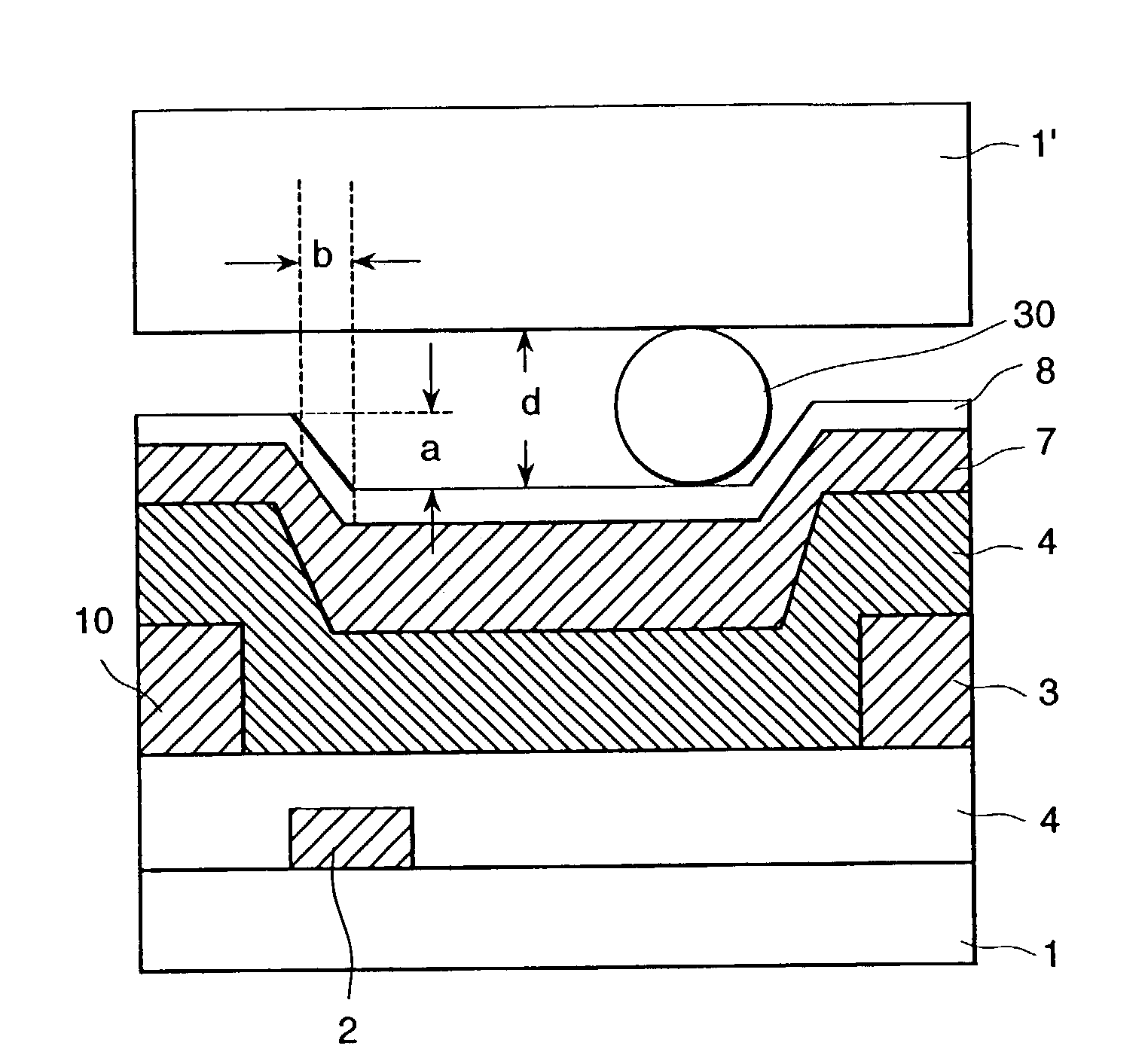
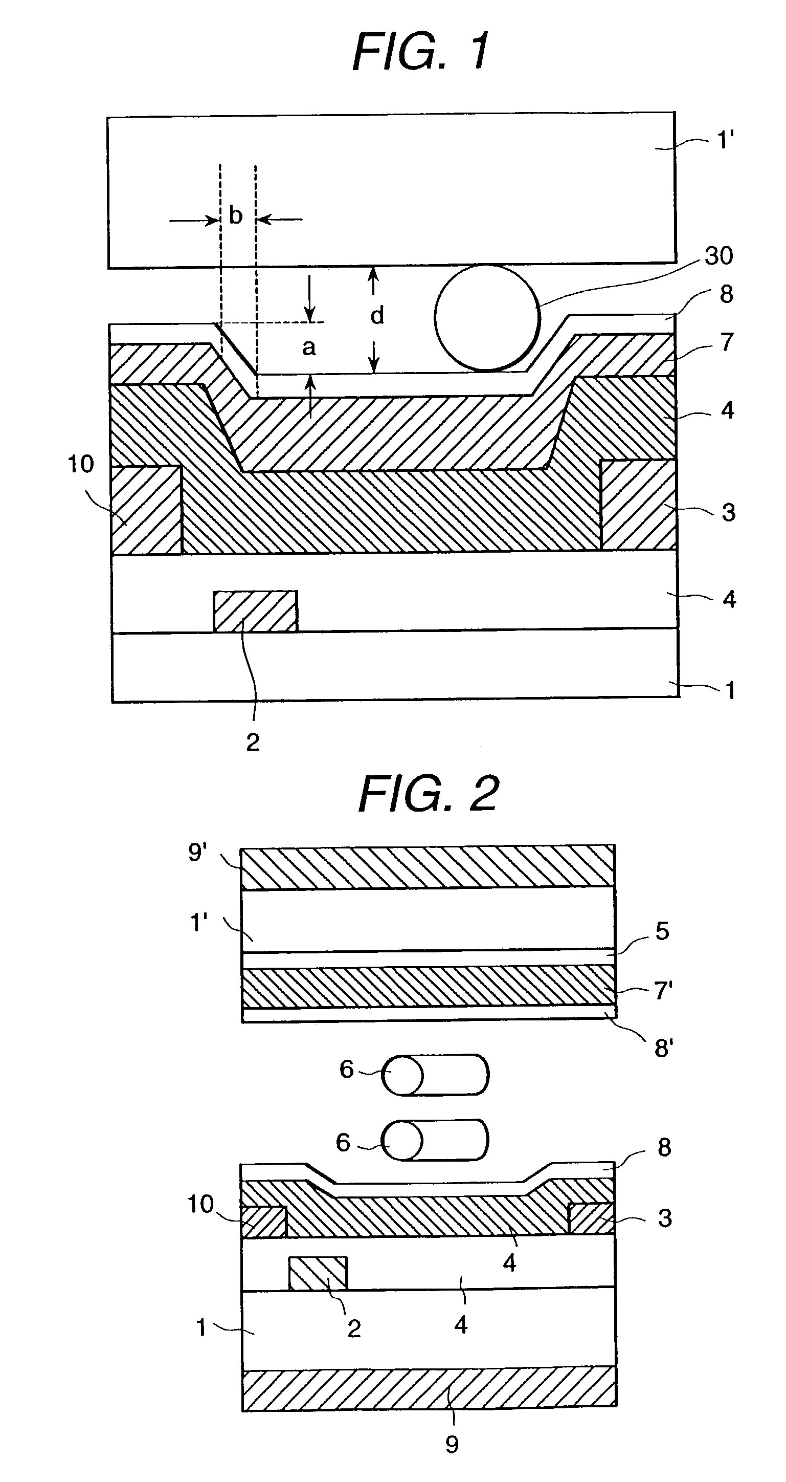
[0036]In FIG. 2, a schematic cross-sectional view of a cell of a liquid crystal display apparatus of this embodiment is shown. Between a pair of transparent substrates 1, 1′ there is disposed a liquid crystal layer 32 composed of plural compounds. In FIG. 2 schematically shows rod shaped liquid crystal molecules 6. On both outer sides of the pair of substrates 1, 1′, polarizing plates 9, 9′ are arranged. On the inside face of a cell of one substrate 1, stripe shaped electrodes 2, 3 are formed, and above this an insulation layer 4 is formed. Above the insulation layer 4, an alignment control layer 8 is formed. The electrode 2 is a common electrode to which a constant waveform voltage which does not depend on an image signal is applied, and the electrode 3 is a pixel electrode that carries a signal above waveform changes in response to the image signal. Further, at the same level as the pixel electrode 3, an image signal electrode 10 is formed. Both the thicknesses of the pixel electr...

embodiment 2

[0050]With respect to Embodiment 1, the following points are different in this embodiment.

[0051]On the other substrate which is arranged opposite to the substrate having the electrode group, a stepped difference structure is added. Further, on this opposite substrate, the color filter is formed and at the boundary portion of the three primary colors of red (R), yellow (Y) and blue (B), a black matrix formed of a mixture of resin material and black color paints is formed. The structure is shown in FIG. 8(a). The thickness of the black matrix is greater than all of the primary colors of the color filter portion. On the black matrix and the primary color portion, similar to the electrode side substrate of Embodiment 1, the alignment control layer 8, to which is added the liquid crystal alignment ability provided by the transparent organic high molecular layer 7 and the polarization light radiation, is coated. Further, as explained with reference to the formula (1), since the liquid cry...

embodiment 3

[0053]In Embodiment 2, the thickness of the black matrix is thicker than all of the primary colors of the color filter portion, but in this embodiment, in contrast, the black matrix portion is formed as the most thin portion, as seen in FIG. 9(a). The other points except the above are the same as the Embodiment 2. As to the black matrix material, a low reflection type three layered chromium layer is used. In this case, the stepped difference a at the surface of the alignment control layer 8 is 0.15 at the maximum. Further, the width b at the taper portion is 0.8 and the ratio a / b is 0.19. The thickness d of the liquid crystal layer is 4.2 microns and the ratio a / d is 0.036.

[0054]With the above structure, when an IPS-TFT-LCD having a diagonal angle of 13.3 inches and a pixel number of 1.024×RGB×768 was manufactured for trial, the contrast ratio was found to exceed 300 extending over the whole face of the device, and a liquid crystal display apparatus having a good display homogeneity...


PUM

PropertyMeasurementUnit
thicknessaaaaaaaaaa
sizeaaaaaaaaaa
sizeaaaaaaaaaa

Abstract

A liquid crystal display apparatus include a pair of substrates, a liquid crystal layer arranged between the pair of substrates; a plurality of electrodes formed on one substrate, and an alignment control layer formed on a face of at least one of the pair of substrates and being in contact with the liquid crystal layer. An optical characteristic is charged in response to a molecular alignment condition of the liquid crystal layer, and the thickness of the liquid crystal layer is set to a substantially constant thickness by spacers. A surface of the alignment control layer on the at least one of the pair of substrates which is in contact with the liquid crystal layer has stepped difference portions and on a surface formed in a display pixel, an inclination degree of a stepped difference portion in said alignment control layer is less than 1.

Description

CROSS REFERENCE TO RELATED APPLICATION[0001]This is a continuation of U.S. application Ser. No. 09 / 423,463, filed Feb. 2, 2000, now U.S. Pat. No. 6,504,591, which is a 371 of PCT application Ser. No. PCT / JP98 / 02049 filed May 8, 1998 the subject matter of which is incorporated by reference herein.TECHNICAL FIELD[0002]The present invention relates to an in-plane switching (In-plane switching: IPS) type liquid crystal display apparatus, in which the electric field is applied to a liquid crystal layer in a direction which is substantially parallel to the substrate of the liquid crystal display apparatus when it is operated. More particularly, the invention relates to a large size display panel having an alignment control layer and which exhibits a good productivity.BACKGROUND OF THE INVENTION[0003]Recently, there has been a strong demand for a liquid crystal display apparatus which has a large size, a wide viewing angle and a multi-color performance. As to the viewing angle characterist...

Claims


Application Information

Patent Timeline
Patent Type & Authority Patents(United States)
IPC IPC(8): G02F1/1337G02F1/1333G02F1/1335G02F1/1339G02F1/1343
CPCG02F1/133788G02F1/134363G02F1/133345G02F1/133371G02F1/133512G02F2001/133776G02F1/13394G02F1/133723G02F1/133776G02F1/1337
Inventor KONDO, KATSUMITOMIOKA, YASUSHIMIWA, TAKAOYONEYA, MAKOTO
Owner PANASONIC LIQUID CRYSTAL DISPLAY CO LTD
Why Eureka
Try Eureka