Method and device for aiming a weapon barrel and use of the device

a weapon barrel and barrel aiming technology, applied in the direction of weapon control systems, aiming means, weapon components, etc., can solve the problems of inability to precisely aim the weapon barrel, the weapon cannot be stably aimed, and the inability to precisely determine the deployment distance by the naked eye, so as to facilitate the replacement of defective devices

Inactive Publication Date: 2006-08-15
CHARTERED AMUNITION IND PTE LTD +1
View PDF15 Cites 36 Cited by
  • Summary
  • Abstract
  • Description
  • Claims
  • Application Information

AI Technical Summary

Benefits of technology

[0040]The device for executing the method of the invention is preferably embodied as a module and arranged in a housing. The housing can be fastened on a weapon at a later time. This makes retrofitting existing weapons possible, as well as the use of a uniform module with different weapons, and furthermore makes the replacement of a defective device easier. Such a housing does not necessarily have to contain all components of the novel device, the angle measuring unit in particular can be arranged somewhere else and can be connected with the data processing unit with the aid of connecting lines.

Problems solved by technology

However, it is almost impossible to exactly determine the deployment distance by the naked eye, therefore a distance range, within which the exact deployment distance is presumed to lie, is generally estimated.
But rear / front sight aiming devices have two large disadvantages, which result in the inability to precisely aim the weapon barrel: for one, the deployment distance is only approximately known in most cases, since it must be estimated by the naked eye; furthermore, there is only a vague image of the target because of the lack of an optical enlargement, and the weapon can therefore not be stably aimed.
If no gun sight angle were to be taken into consideration, this would lead to corresponding inaccuracies.
This problem becomes more serious in connection with slow-flying projectiles, such as grenades, since the long flying time of such projectiles demands a comparatively large gun sight angle.
Essentially, the disadvantages of the image visualization unit in the form of a telescopic sight are the following: The orientation of the telescopic sight parallel with the weapon barrel limits the selection of the enlargement; a gun sight angle, which must be set at the weapon, determines the deviation between the aiming line and the weapon barrel axis, by means of which a target marker is displayed; if the deployment distance is too great, these gun sight angles are relatively large, which has the result that the target marker can no longer be displayed in an optical device capable of considerable enlargement.
Moreover, distortions are received in case of too large a deviation, unless an optical device is employed which is absolutely free of distortion and therefore expensive.
However, the use of ABM can only be successful if it is possible to accurately determine the projectile trajectories, or when the weapons used have devices which permit the exact sighting of the target and aiming of the weapon barrel.
However, the technology of these very elaborate weapons systems cannot be transferred to infantry weapons, which should be simple in construction and handling, cost-effective, light and mobile to the highest degree, and must operate autonomously.

Method used


Image

  • Method and device for aiming a weapon barrel and use of the device
  • Method and device for aiming a weapon barrel and use of the device
  • Method and device for aiming a weapon barrel and use of the device

Examples


Embodiment Construction

[0050]In what follows, the same reference symbols will be used for like elements in all drawing figures, even if these elements differ in detail. The drawings are not to scale. Aiming is understood in what follows to be the movement of the weapon barrel, respectively together with the image visualization unit; sighting is understood to be the movement of the image visualization unit in respect to the weapon barrel.

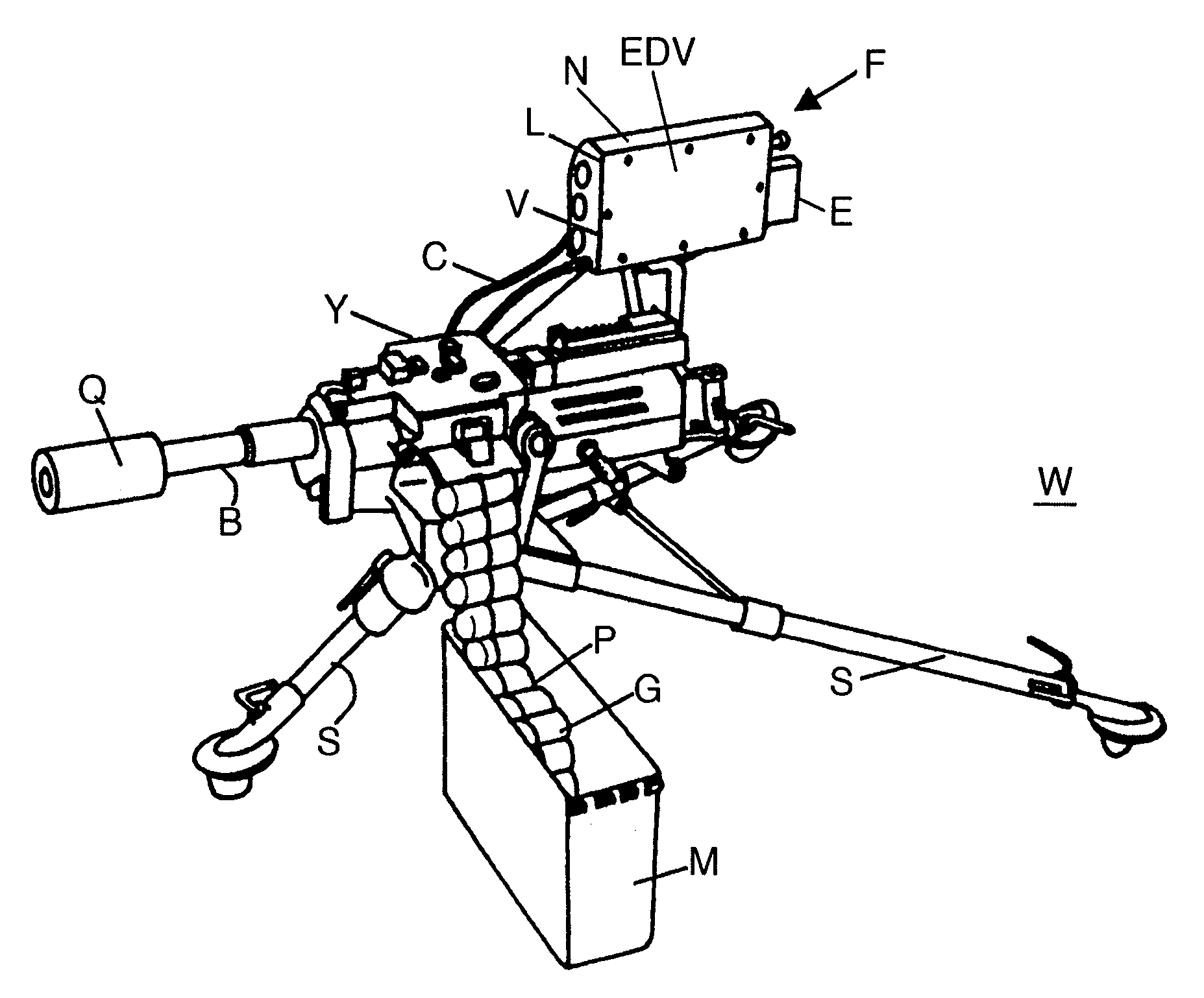
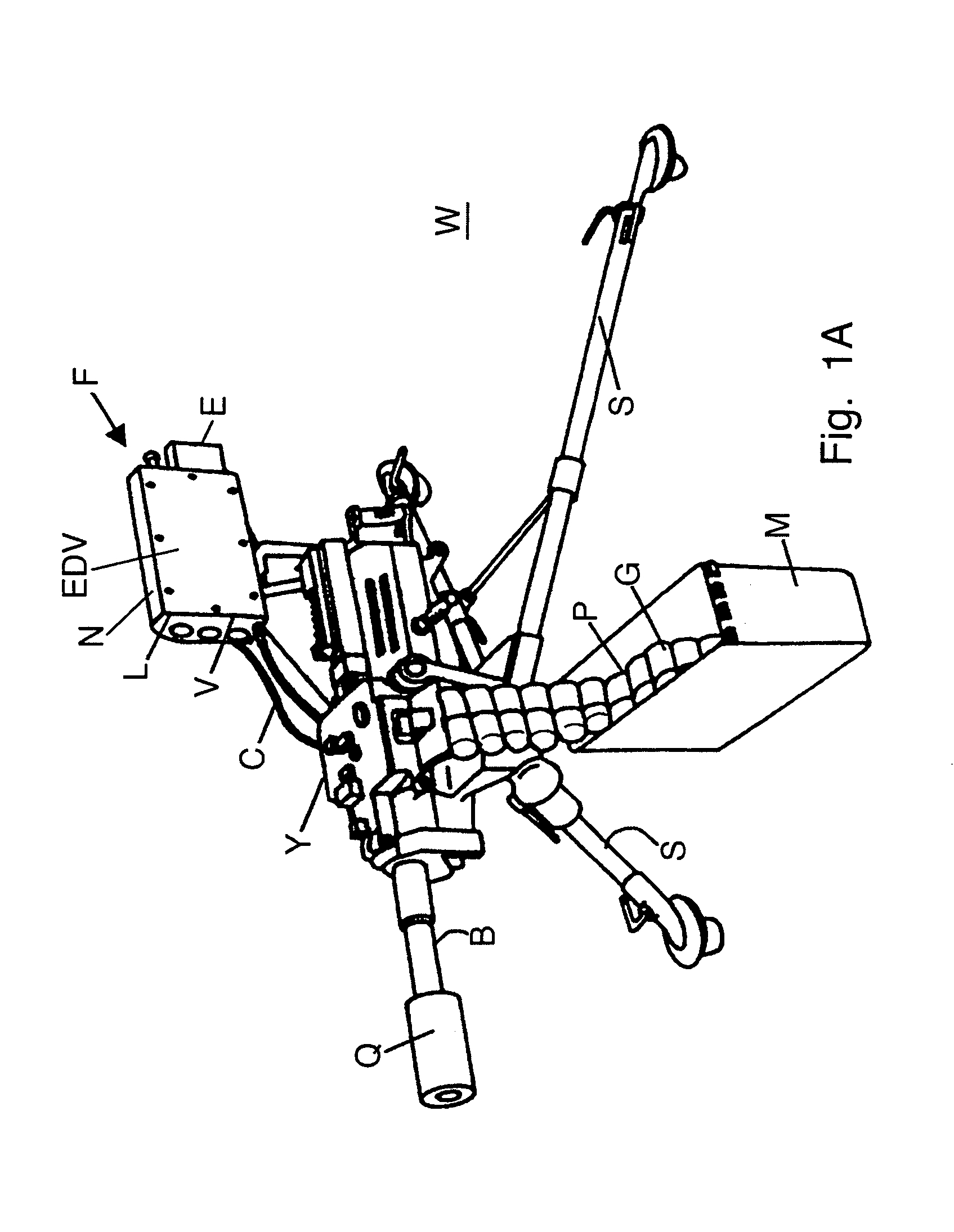
[0051]The weapon W represented in FIG. 1A has a weapon barrel B with a weapon barrel axis b, which is often also called the bore axis, and a support structure in the form of a tripod mount S. The weapon W has a programming unit Q, by means of which projectiles P to be fired can be programmed, or their fuses timed. In the instant case the programming unit Q is arranged at the front end of the weapon barrel B, however, it could also be positioned elsewhere. The weapon barrel B is fastened on the tripod mount S in such a way that its elevation and azimuth can be changed in re...


PUM


Abstract

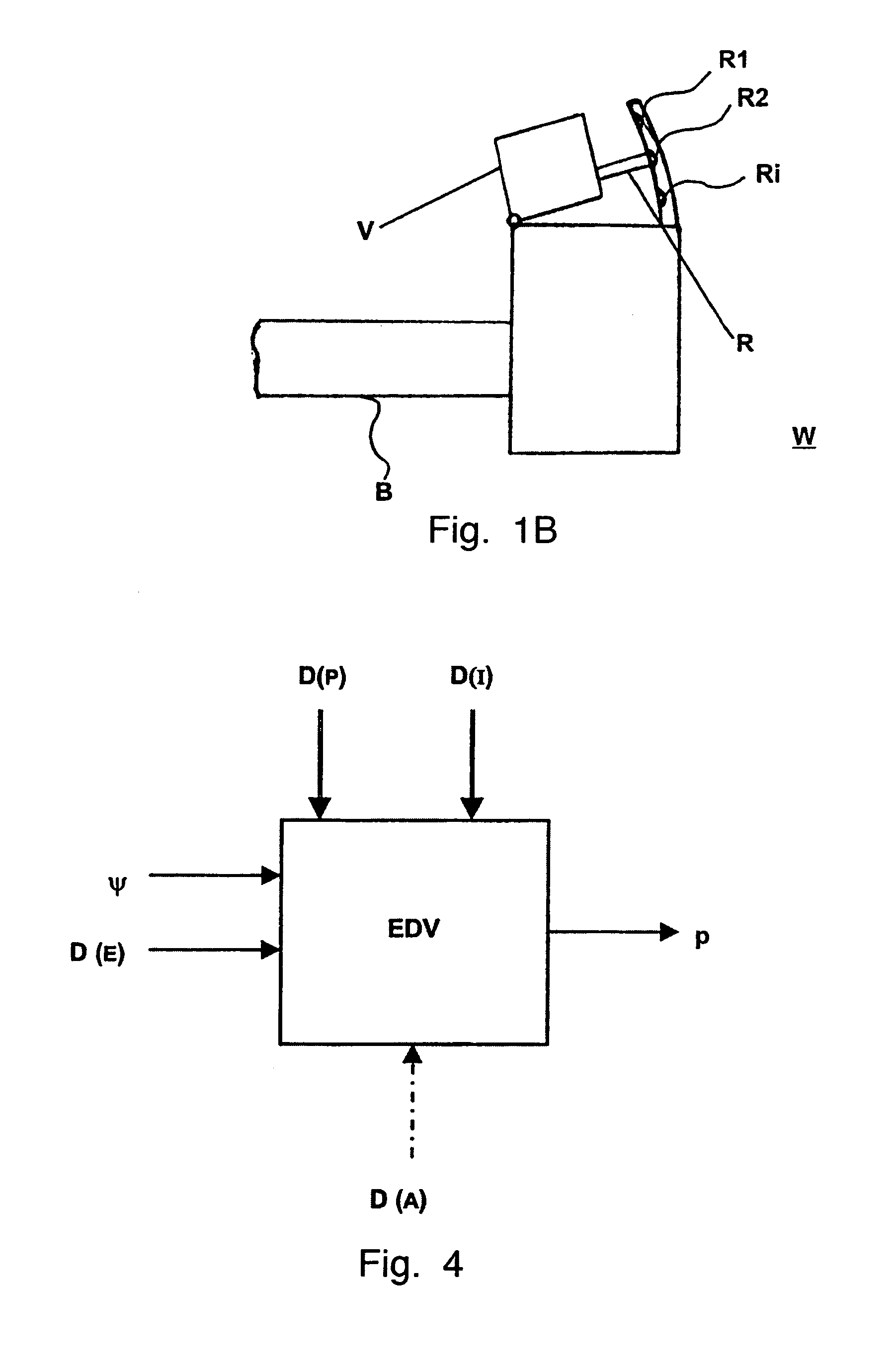
A method for aiming a weapon barrel [B], wherein a target image [Z*] and a target marker [X] are displayed with the aid of an image visualization unit M. The rough aiming of the weapon barrel [B] is performed in a first phase, in a second phase, with the weapon barrel [B] stationary, sighting by sighting the target image [Z*] by means of the image visualization unit [V] is performed, wherein the target image [Z*] and the target marker [X] are brought into coincidence as closely as possible, and fine aiming of the weapon barrel [B] in a third phase. The device for executing the method comprises a device for setting an initial gun sight angle [ψo] an image visualization unit [V], the latter displays a target image [Z*] and a target marker [X] representing the end of an imaginary projectile trajectory [p]. The device contains a fire control device, with the image visualization unit [V], an angle measuring device [Y] for measuring angular changes [Δψ] and a data processing unit [EDV] for performing a ballistics calculation, in which the angular change [Δψ] and the interior ballistics can be taken into consideration, as well as for issuing a signal determining the target marker [X]. The device is suitable for infantry weapons.

Description

CROSS REFERENCE TO RELATED APPLICATION[0001]Applicant hereby claims foreign priority under 35 U.S.C. § 119 from Swiss Patent Application No. 2001 1880 / 01, filed 12 Oct. 2001, the disclosure of which is herein incorporated by reference.FIELD OF THE INVENTION[0002]The invention relates to a method for aiming a weapon, having a weapon barrel with a weapon barrel axis, on a target, wherein a target image representing the target, and a target marker representing the end of a projectile trajectory, are displayed with the aid of an image visualization unit. The invention further relates to a device for executing the method, as well as to the use of the device.BACKGROUND OF THE INVENTION[0003]When firing infantry weapons, such as rifles, assault rifles, grenade launchers and mortars, aiming of the weapon barrels is performed manually in most cases by aiming at the target without the aid of a fire control device.[0004]Prior to firing it is necessary to set a gun sight angle at the weapon, wh...

Claims


Application Information

Patent Timeline
Patent Type & Authority Patents(United States)
IPC IPC(8): F41G5/06F41G3/06F41G3/14
CPCF41G3/142F41G3/06
Inventor FRIEDLI, ANDREASOBERHOLZER, MARKUSBERTHOLET, MARCHOK, AW CHENGHIM, NG SAY
Owner CHARTERED AMUNITION IND PTE LTD
Why Eureka
Try Eureka