Vibration control arrangement for internal combustion engines

a technology for internal combustion engines and vibration control, which is applied in the direction of machines/engines, bearing unit rigid supports, valve drives, etc., can solve the problems of increased stress on the motor, increased vibration, and poor resistance of vibration control materials such as rubber and plastic to deformation, so as to increase the stress on the engine and cause more vibration

Inactive Publication Date: 2006-08-15
HONDA MOTOR CO LTD
View PDF15 Cites 3 Cited by
  • Summary
  • Abstract
  • Description
  • Claims
  • Application Information

AI Technical Summary

Benefits of technology

[0006]In view of such problems of the prior art, a primary object of the present invention is to provide a vibration control arrangement for internal combustion engines that are both effective and durable.
[0007]A second object of the present invention is to provide a vibration control arrangement for internal combustion engines that are both effective and economical.
[0008]A third object of the present invention is to provide a vibration control arrangement for internal combustion engines that would not impair the performance of the engine and is reliable is use.
[0010]The vibration control alloy has a vibration isolation capability comparable to that of rubber, but provides a durability and a resistance to degradation comparable to those of metal and alloy that are typically used in internal combustion engines. Therefore, a desired vibration control can be achieved while ensuring a required reliability, durability and resistance to degradation. The present invention is particularly useful when the valve actuating mechanism is provided with a variable lift, variable timing or variable compression mechanism because such a variable mechanism increases the stress to the engine, and tends to cause more vibrations than a more conventional non-variable valve actuating mechanism.

Problems solved by technology

In particular, when variable mechanisms such as variable valve lift mechanism, variable valve timing mechanism, a variable compression ratio mechanism, etc. is used, the adjusting mechanism tends to apply an additional stress to various parts of the engine, and the vibration problems often become even more acute.
Firstly, the vibrations owing to the collision between the valve and the valve engagement portion of the rocker arm are transmitted to the cam holder via the rocker arm.
Secondly, the vibrations owing to the collision between the cam and cam engagement portion of the rocker arm are transmitted to the cam holder via the rocker arm or camshaft.
However, the vibration control material such as rubber and plastic has a poor resistance to deformation and prone to degradation as compared with metallic material such as an aluminum alloy which is typically used in various components of the engine.

Method used


Image

  • Vibration control arrangement for internal combustion engines
  • Vibration control arrangement for internal combustion engines
  • Vibration control arrangement for internal combustion engines

Examples


Embodiment Construction

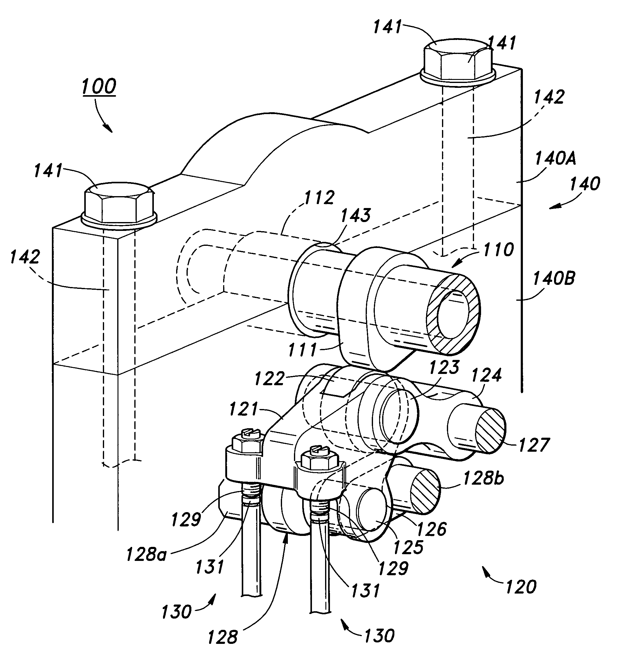
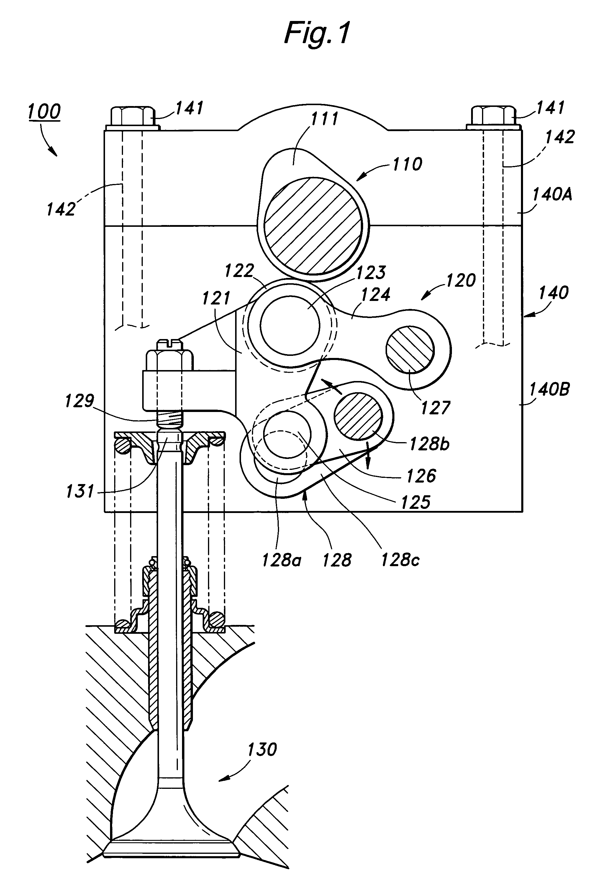
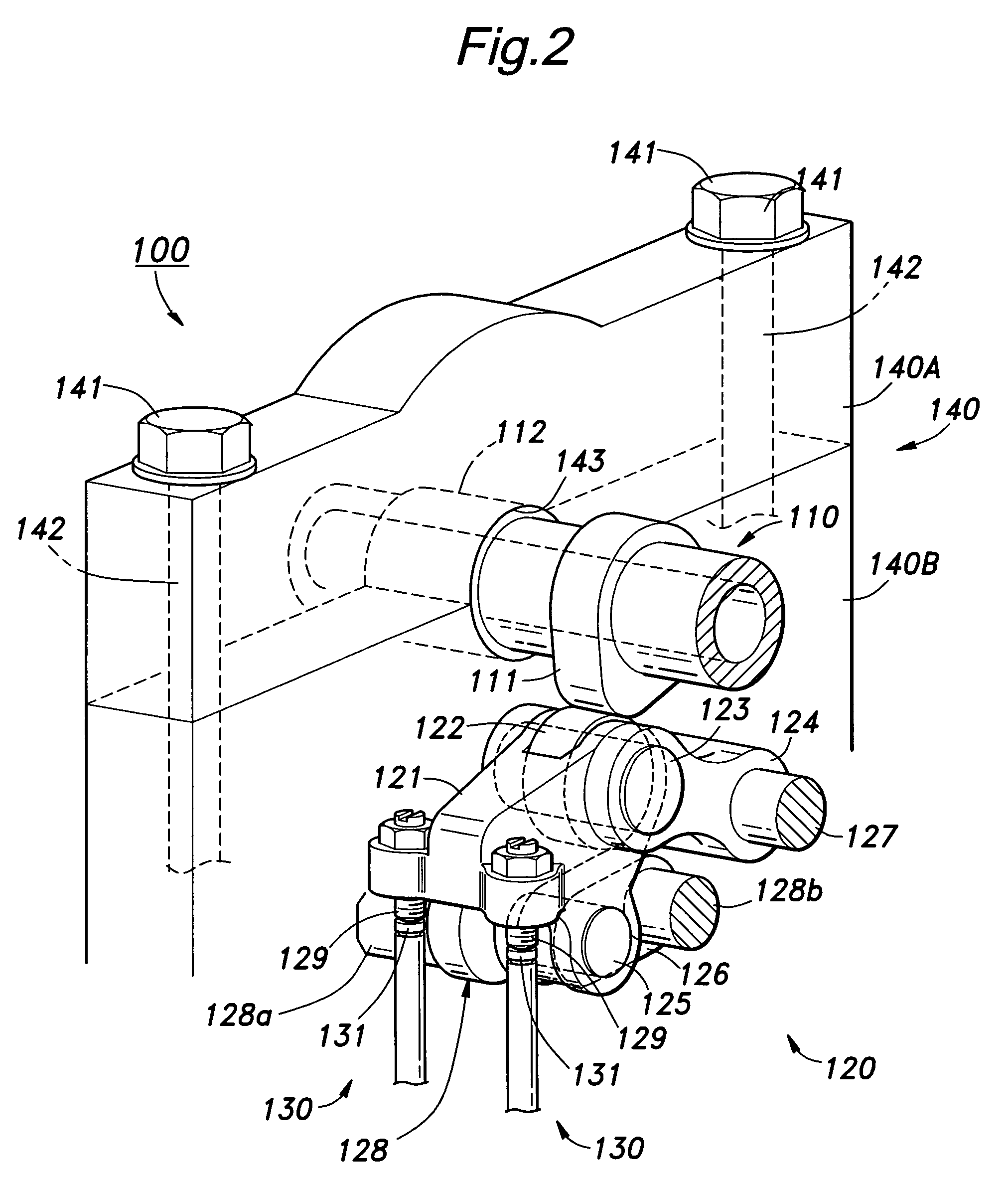
[0034]The present invention is characterized by the fact that the parts of an engine valve system or crankshaft system that would transmit vibrations from vibration sources are made of vibration control alloy to effectively attenuate the transmission of vibrations. In the case of a valve actuating mechanism, the vibrations are typically produced as a result of impulsive contacts between each cam and the cam follower part of a corresponding rocker arm and between the valve stem of each valve and the valve stem engaging part of the corresponding rocker arm. In the case of a crankshaft system, as the combustion occurs and the resulting pressure pushes a piston, the plays that may be present in the path of power transmission between the piston and a crankshaft are impulsively closed, and this produces vibrations in various parts of the path of power transmission.

[0035]The vibration control alloy as used in this application includes, not exclusively, Mn—Cu and Fe—Al vibration control all...


PUM


Abstract

In an internal combustion engine including a valve actuating mechanism, a vibration control member made of vibration control alloy is interposed in a path of vibration transmission between a camshaft and a cylinder head. The vibration control alloy has a vibration isolation capability comparable to that of rubber, but provides a durability and a resistance to degradation comparable to those of metal and alloy that are typically used in internal combustion engines. Therefore, a desired vibration control can be achieved while ensuring a required reliability, durability and resistance to degradation. The present invention is particularly useful when the valve actuating mechanism is provided with a variable lift, variable timing or variable compression mechanism because such a variable mechanism increases the stress to the engine, and tends to cause more vibrations than a more conventional non-variable valve actuating mechanism.

Description

TECHNICAL FIELD[0001]The present invention relates to a vibration control arrangement for internal combustion engines, and in particular to a vibration control arrangement that is effective in reducing the transmission of vibrations from vibration sources in the valve actuation system and / or piston-crank system of an internal combustion engine.BACKGROUND OF THE INVENTION[0002]The valve actuation system of an internal combustion engine for opening and closing intake valves and exhaust valves typically uses rocker arms that are each provided with a cam engagement portion for engaging a cam formed on a camshaft and a valve engagement portion for engaging the stem end of a valve. The camshaft is rotatably supported by a cam holder provided on the cylinder head, and a rocker arm shaft that rotatably supports the rocker arm is fixed to the cam holder. In such a valve actuating mechanism, vibrations that are produced as a result of actuation of the valve are transmitted to the outside, and...

Claims


Application Information

Patent Timeline
Patent Type & Authority Patents(United States)
IPC IPC(8): F16C9/00F01L1/04F01L1/00F01L1/02F01L1/18F01L1/34F01L1/46F01L13/00F02D15/02F02F1/24F02F7/00F16C9/02F16C33/12F16F15/02
CPCF01L1/46F01L13/0015F01L1/16F01L1/182F01L1/20F01L2101/00F01L2001/0476F01L1/267F01L2810/03F01L2301/00
Inventor FUJII, NORIAKIYONEKAWA, AKIYUKINAKAMURA, KATSUNORIYOSHIDA, KEIKONAGAKURA, MASAKIFUJIMOTO, TOMOYA
Owner HONDA MOTOR CO LTD
Why Eureka
Try Eureka