
Radioisotope generator

a radioisotope generator and generator technology, applied in nuclear engineering, separation processes, instruments, etc., can solve the problems of destroying the aseptic environment, tearing the stopper, and limiting the application of piercing devices in general to intravenous systems

Inactive Publication Date: 2006-08-15
GE HEALTHCARE LTD
View PDF13 Cites 46 Cited by
  • Summary
  • Abstract
  • Description
  • Claims
  • Application Information

AI Technical Summary

Benefits of technology

[0010]The present invention seeks to provide a radioisotope generator that is simple in construction but which ensures the necessary degree of sterility and radiological protection is maintained during use.
[0012]Thus, with the present invention rotational movement of a vial penetrated by the spike would not result in tearing of the rubber seal in a manner that would result in the ingress of unfiltered air. Thus, this construction of radioisotope generator ensures that the aseptic conditions of the generator are maintained during use.

Problems solved by technology

Moreover, due to the fact that the isotope used in the ion exchange column of the generator is radioactive, and is thereby extremely hazardous if not handled in the correct manner, the radioisotope generation process also should be performed under radiologically safe conditions.
The dispensing device is intended to penetrate an elastic stopper and so presents the problem that any rotational movement of the eluant container will result in tearing of the stopper which in turn destroys the aseptic environment through the uncontrolled introduction of air into the system.
Although piercing devices are known that employ a single spike with two channels such as that illustrated in U.S. Pat. No. 4,211,588 such piercing devices have been restricted in their application in general to intravenous systems.

Method used


Image

  • Radioisotope generator
  • Radioisotope generator
  • Radioisotope generator

Examples


Embodiment Construction

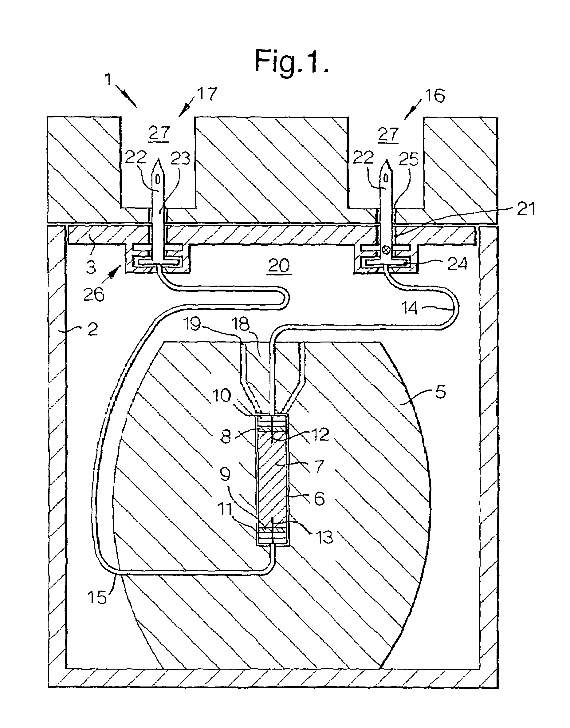
[0016]FIG. 1 illustrates a radioisotope generator 1 comprising an outer container 2, a top plate 3 which is sealingly secured to the outer container 2, and a separate top cover 4 which is secured to the outer container 2 over the top plate 3. Inside the outer container 2 an inner shielded container 5, providing shielding against radiation, is located which is preferably, but not exclusively, made from either lead or a depleted uranium core within a stainless steel shell. The shielded container 5 surrounds a tube 6 containing an ion exchange column 7. The ion exchange column 7 preferably consists of a mixture of aluminium and silica, onto which molybdenum in the form of its radioactive isotope, 99Mo is adsorbed. The tube 6 containing the ion exchange column has frangible rubber seals 8 and 9 at opposing ends 10 and 11 which, as illustrated, when in use are pierced by respective hollow needles 12 and 13.

[0017]Each of the hollow needles 12 and 13 is in fluid communication with a respec...


PUM


Abstract

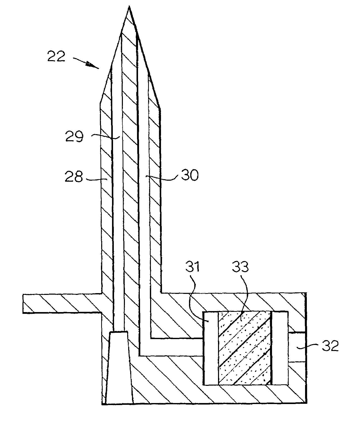
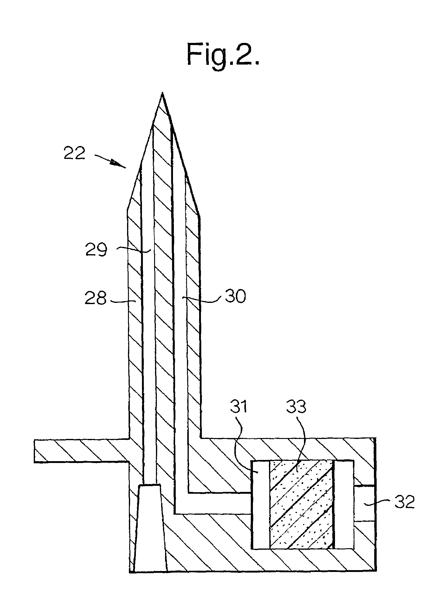
The invention relates to a device for producing a fluid containing a radioactive constituent, the device comprising: a shielded chamber (5) within which is located an isotope container (6) housing a radioactive isotope (7), the shielded chamber including first and second fluid connections (12,13) to opposing ends of the isotope container and a fluid conduit (14,15) extending from each of the first and second fluid connections to a fluid inlet (16) and a fluid outlet (17) respectively characterised in that the fluid inlet comprises a single spike (22) having a substantially circular cross-section, the spike being adapted to penetrate the rubber seal of a vial and the spike having two bores, the first bore extending from a first aperture adjacent the tip of the spike to a fluid connection with the fluid conduit and the second bore extending from a second, separate aperture in the spike to a filtering air inlet.

Description

[0001]This application is a filing under 35 U.S.C. 371 of international application number PCT / GB02 / 05613, filed Dec. 11, 2002, which claims priority to application number 0208354.1 filed Apr. 11, 2002, in Great Britain the entire disclosure of which is hereby incorporated by referenceFIELD OF INVENTION[0002]The present invention relates to a radioisotope generator of the type commonly used to generate radioisotopes such as metastable technetium-99m (99mTc).BACKGROUND OF THE INVENTION[0003]The diagnosis and / or treatment of disease in nuclear medicine constitute one of the major applications of short-lived radioisotopes. It is estimated that in nuclear medicine over 90% of the diagnostic procedures performed worldwide annually use 99mTc labelled radio-pharmaceuticals. Given the short half-life of radio-pharmaceuticals, it is helpful to have the facility to generate suitable radioisotopes on site. Accordingly, the adoption of portable hospital / clinic size 99mTc generators has greatly ...

Claims


Application Information

Patent Timeline
IPC IPC(8): G21G4/08G21G1/00A61N5/10G21F5/015
CPCG21G4/08G21F5/015
Inventor WEISNER, PETER STEWARTFORREST, TERENCE ROBERT FREDERICK
Owner GE HEALTHCARE LTD
Learn More