BWR inspection manipulator

a manipulator and bwr technology, applied in the direction of nuclear elements, nuclear engineering problems, greenhouse gas reduction, etc., can solve the problems of lowering the water level in the reactor vessel and exposing the core, fuel assemblies may become overheated and damaged, and other core components may be damaged, corrosion cracking of the spray sparger and other sections of the core spray supply pipe,

Inactive Publication Date: 2006-08-15
WESTINGHOUSE ELECTRIC CORP
View PDF14 Cites 29 Cited by
  • Summary
  • Abstract
  • Description
  • Claims
  • Application Information

AI Technical Summary

Benefits of technology

[0009]Accordingly, it is an object of this invention to provide a method and apparatus that would reduce inspection time of components in the areas around the core shroud.
[0010]It is a further object of this invention to provide a method and apparatus that will increase the quality of the data gathered during visual inspections of the areas surrounding the core shroud.
[0012]Further, it is an object of this invention to provide a method and apparatus that can provide a remote visual inspection of the area surrounding the core shroud without obstructing refueling.
[0013]These and other objects are achieved by a remotely operated system employing a motorized trolley assembly configured to ride on an upper lip of the core shroud or other tubular member to be inspected. A vertically oriented support column assembly having a first portion rotatably mounted on the trolley and at least one laterally extending arm extending from the first part, such that rotation of the column assembly positions a peripheral end portion of the laterally extending arm on an inboard side or an outboard side of the underlying tubular body. An extendable pole assembly having a first end attached to the laterally extending arm and having a plurality of telescoping sections nested in the second end for extending from the second end to a preselected elevation below the upper lip of the core shroud. An adjustable camera or other tool is attached to the second part of the extendable pole assembly via an arcuate track that can guide a camera around a 180° arc. Preferably, the trolley is supported by a 360° circular track that is seated on top of the core shroud lip. The track assembly is formed in sections for ease of shipment and can be adjusted to fit different diameter shrouds. Preferably, the motorized trolley includes a remotely operated cam that, when rotated, clamps onto the track to aid stability.
[0016]A second camera can be positioned on a moveable carriage, extendable along a track to position the camera above the support column assembly to provide an overview of the operation of the tool. The tool can thus accomplish inspections without obstructing the core so as to enable refueling to be performed in parallel with the visual inspections.

Problems solved by technology

In a Loss Of Coolant Accident (LOCA), rupturing of the recirculation duct system or the steam duct system during operation can cause coolant water to flow out of the reactor vessel, thereby lowering the water level in the reactor vessel and exposing the core such that the fuel assemblies may become overheated and damaged.
After periods of use, intergranular stress corrosion cracking of the core spray spargers and other sections of the core spray supply piping as well as other core components tends to occur as a result of corrosion, radiation and stress.
Such cracking can lead to crack opening widths which permit significant leakage from the core spray spargers and the core spray supply piping.
Leakage from the core spray spargers inside the shroud is typically not considered to be a major problem; however, when significant leakage from the core spray supply piping occurs outside the shroud, the piping must either be replaced or repaired.
Cracking can also occur in the welds joining other components such as the jet pumps.
This is usually accomplished through visual inspections which form part of the critical path of an outage, since it typically obstructs refueling of the core.

Method used


Image

  • BWR inspection manipulator
  • BWR inspection manipulator
  • BWR inspection manipulator

Examples


Embodiment Construction

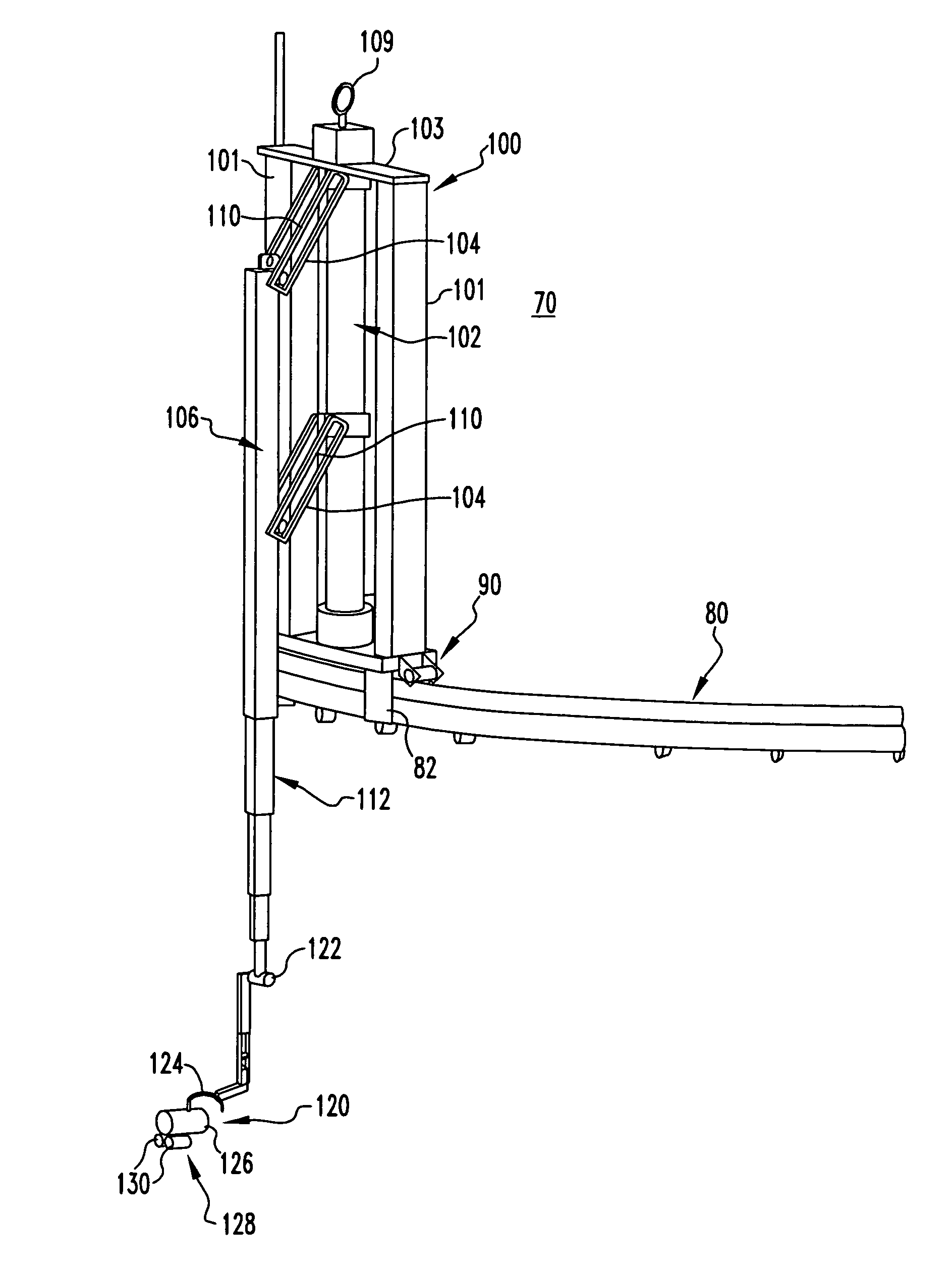
[0025]The service manipulator delivery system of this invention is a remotely operated trolley system 70 that operates on the top lip or steam dam 68 of a BWR shroud or track 80 attached to the shroud 18. The trolley system 90 supports a mast 102 and a pole system 106 designed to mount a TV camera assembly 120 for inspection of various reactor components at the same time that fuel is being moved within or into or out of the core. This allows two operations to be performed in the reactor at the same time, saving time.

[0026]During a BWR or PWR refueling outage, much of the work in the reactor is performed on a critical path. Formerly, visual inspections were performed at a different time than fuel movement because the same equipment, e.g., the refueling bridge, was needed for both tasks. By utilizing a remote controlled unit, such as that of this invention, that does not interfere with the fuel movement path to hold the visual inspection equipment, the operations can be done in tandem...


PUM


Abstract

A reactor service manipulator delivery system supported on a remotely operated trolley that travels on top of a track attached to the steam dam of a BWR shroud. The trolley has a mast and pulley system designed to manipulate a TV camera for inspection of various reactor components inboard and outboard of the shroud at the same time that fuel is being moved within the core during a refueling operation so that refueling can be performed in parallel with the inspection.

Description

CROSS REFERENCE TO RELATED APPLICATION[0001]This application is a Continuation-in-Part of Provisional Applications U.S. Ser. No. 60 / 415,454, filed Oct. 1, 2002 and U.S. Ser. No. 60 / 440,187, filed Jan. 15, 2003.BACKGROUND OF THE INVENTION[0002]This invention pertains in general to nuclear reactor service manipulators and more particularly to a manipulator supportable on a BWR reactor shroud which can inspect the areas adjacent the shroud without obstructing refueling.RELATED ART[0003]A boiling water nuclear reactor 10, as illustrated in FIG. 1, includes a reactor vessel 12, a core 14 made up of a plurality of fuel assemblies 16, and a core shroud 18 disposed concentrically within the reactor vessel around the core. Core shroud 18 typically includes upper and lower cylindrical sections 20 and 22 connected by a horizontal plate 24 extending radially inward from a bottom edge of the upper cylindrical section to an upper edge of the lower cylindrical section. A shroud head flange is weld...

Claims


Application Information

Patent Timeline
Patent Type & Authority Patents(United States)
IPC IPC(8): G21C17/003B65H1/00
CPCG21C17/003G21C17/013G21Y2002/202G21Y2002/203G21Y2004/504G21Y2002/304G21Y2002/401G21Y2004/501G21Y2002/204Y02E30/30
Inventor WIVAGG, ADRIAN PETERBOONE, PAUL JOSEPHRADOVICH, SR., PAUL R.
Owner WESTINGHOUSE ELECTRIC CORP
Why Eureka
Try Eureka