Apparatus and methods for generating radio frequencies in communication circuitry using multiple control signals
- Summary
- Abstract
- Description
- Claims
- Application Information
AI Technical Summary
Benefits of technology
Problems solved by technology
Method used
Image
Examples
embodiment 400
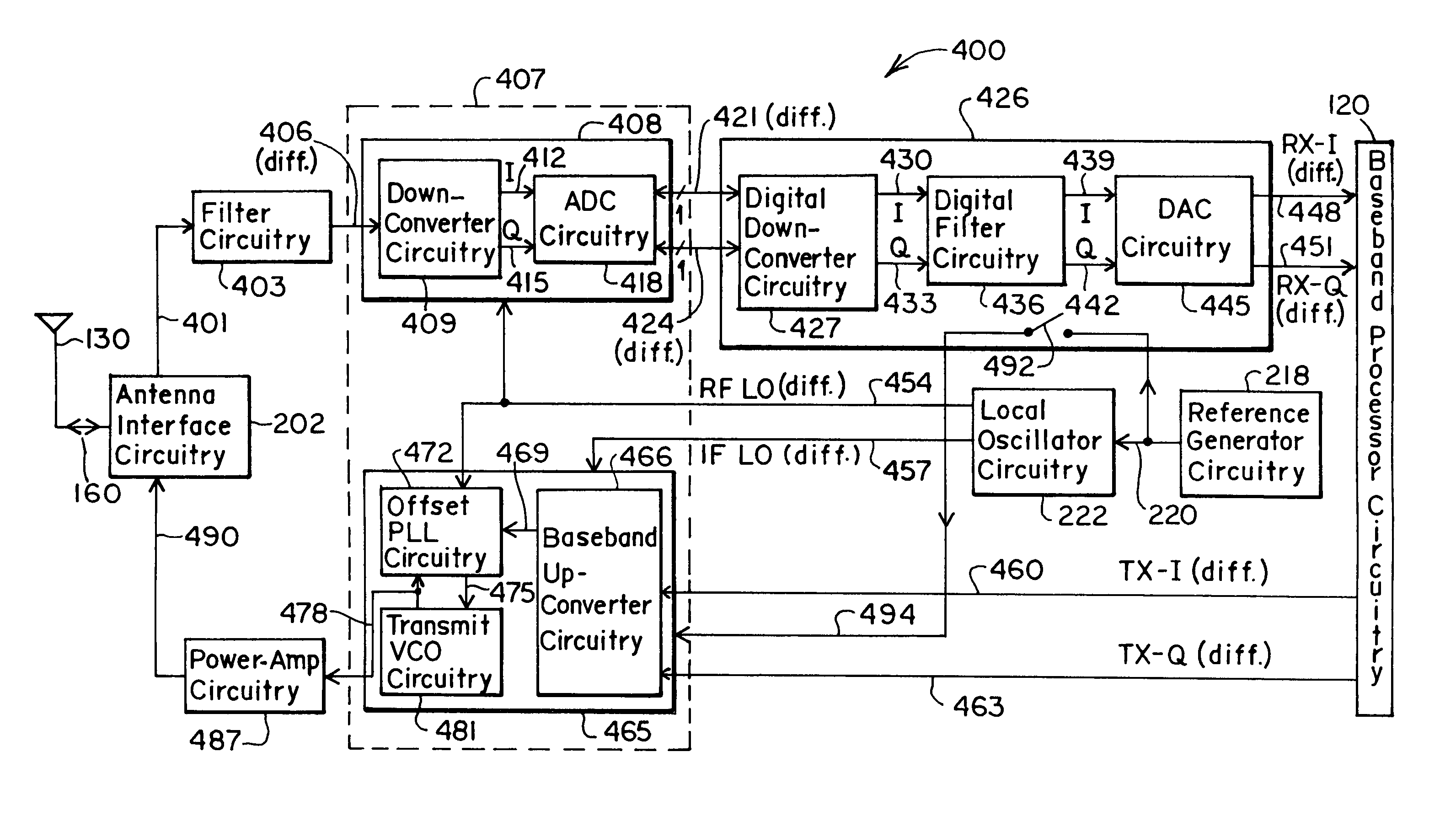
[0078]FIG. 4 shows a more detailed block diagram of an embodiment 400 of an RF transceiver partitioned according to the invention. The transceiver includes receiver analog circuitry 408, receiver digital circuitry 426, and transmitter circuitry 465. In the receive mode, the antenna interface circuitry 202 provides an RF signal 401 to a filter circuitry 403. The filter circuitry 403 provides a filtered RF signal 406 to the receiver analog circuitry 408. The receiver analog circuitry 408 includes down-converter (i.e., mixer) circuitry 409 and analog-to-digital converter (ADC) circuitry 418. The down-converter circuitry 409 mixes the filtered RF signal 406 with an RF local oscillator signal 454, received from the local oscillator circuitry 222. The down-converter circuitry 409 provides an in-phase analog down-converted signal 412 (i.e., I-channel signal) and a quadrature analog down-converted signal 415 (i.e., Q-channel signal) to the ADC circuitry 418.
[0079]The ADC circuitry 418 conve...
embodiment 700
[0098]Because the embodiment 700 includes the function of the receiver digital circuitry 426 within the baseband processor circuitry 120, it includes two circuit partitions, or circuit blocks. A first circuit partition 710 includes the receiver analog circuitry 408 and the transmitter circuitry 465. A second circuit partition comprises the local oscillator circuitry 222. Note also that, similar to the RF transceiver shown in FIG. 2C, one may also include within the baseband processor circuitry 120 the functionality of the reference generator circuitry 218, as desired.
[0099]FIG. 8 shows an embodiment 800 of a multi-band RF transceiver, partitioned according to the invention. Preferably, the RF transceiver in FIG. 8 operates within the GSM (925 to 960 MHz for reception and 880–915 MHz for transmission), PCS (1930 to 1990 MHz for reception and 1850–1910 MHz for transmission), and DCS (1805 to 1880 MHz for reception and 1710–1785 MHz for transmission) bands. Like the RF transceiver in F...
embodiment 800
[0120]Like the transceiver in FIG. 4, if the receiver digital circuitry 851 need not be compatible with the common analog interface to baseband processors, one may remove the DAC circuitry 875A and 875B, and use a digital interface to the baseband processor circuitry 120, as desired. In fact, similar to the RF transceiver shown in FIG. 2D, one may realize the function of the receiver digital circuitry 851 within the baseband processor circuitry 120, using hardware, software, or a combination of hardware and software. In that case, the RF transceiver would include two circuit partitions, or circuit blocks. The first circuit partition 801 would include the receiver analog circuitry 839 and the transmitter circuitry 877. A second circuit partition would comprise the local oscillator circuitry 222. Note also that, similar to the RF transceiver shown in FIG. 2C, in the embodiment 800, one may include within the baseband processor circuitry 120 the functionality of the reference generator...
PUM
 Abstract
Description
Claims
Application Information
 - R&D
- Intellectual Property
- Life Sciences
- Materials
- Tech Scout
- Unparalleled Data Quality
- Higher Quality Content
- 60% Fewer Hallucinations
Browse by: Latest US Patents, China's latest patents, Technical Efficacy Thesaurus, Application Domain, Technology Topic, Popular Technical Reports.
© 2025 PatSnap. All rights reserved.Legal|Privacy policy|Modern Slavery Act Transparency Statement|Sitemap|About US| Contact US: help@patsnap.com


