
Apparatus for obtaining combustion gases of high calorific value

a combustion gas and apparatus technology, applied in the direction of combustible gas production, gasification process details, inorganic chemistry, etc., can solve the problems of complicated gas cleaning system, heat exchangers in the reaction zone predetermining the dimension of the reaction zone and the fluidized bed, heat exchange surfaces, etc., to simplify the construction of the reactor, improve the heat transfer from the heat exchanger to the heating zone, and ensure the separation of the heating zon

Inactive Publication Date: 2006-08-22
STEER THOMAS
View PDF6 Cites 9 Cited by
  • Summary
  • Abstract
  • Description
  • Claims
  • Application Information

AI Technical Summary

Benefits of technology

[0026]Advantageously, there is no heating means in the reaction chamber in the method according to the invention and in the apparatus according to the invention. Corrosion problems that have so far existed are thereby avoided. Moreover, the inventive method and the inventive apparatus are not limited to special heating means, but permit the use of any desired heating means, in particular tubular heat exchangers. Advantageously, no fuel particles pass from the reducing zone into an oxidizing zone. Moreover, the reaction chamber can be designed independently of the geometrical dimensions predetermined for the heating means, so that the constructional size of the apparatus according to the invention can be optimized.
[0029]In a preferred first embodiment of the apparatus according to the invention, the heating zone and the reaction zone may be separated by way of different fluidization of the fluidized bed, the different fluidization effecting a circulation of the bed material about one or several substantially horizontal axes. The substantially horizontal axes may be closed in the form of a ring. Said embodiment of the apparatus according to the invention is particularly characterized by a compact construction. In a second embodiment of the apparatus according to the invention, the heating zone and the reaction zone are separated by a wall. Moreover, the heating zone and the reaction zone may each be formed in a separate reactor. These two embodiments offer the advantage of a reliable separation of the heating zone from the reaction zone by constructional measures. The means for transferring the heated solid particles may be a wall opening or a pipe. Furthermore, said means for transferring the heated solid particles may be provided in a lower region of the heating zone. In a preferred embodiment, said means comprises a nozzle bottom with the help of which the solid particles can be slightly fluidized in the heating zone.
[0031]In another embodiment, the means for producing the ascending fluidized bed is a nozzle bottom provided in a lower portion of the reaction zone. Such a nozzle bottom offers the advantage of a uniform injection of the fluidizing medium into the reaction zone.

Problems solved by technology

Said method has the drawback that the transportation of the solids between the beds must coincide with the heat balance of the beds, which makes great demands on the control units at high working temperatures and different load conditions.
Furthermore, as far as the fuels are concerned, there is no separation between the combustion region and the gasification region, so that possible pollutants from the fuel may be found along both the gasification path and the combustion path, which complicates the gas cleaning system.
The drawback of such a concept is that the arrangement of the heat exchangers in the reaction zone predetermines the dimension of the reaction zone and the fluidized bed, respectively, because of the heat exchange surfaces required.
Moreover, the heat exchange surfaces are directly exposed to the corrosive effects of harmful constituents of the fuel, which makes extreme demands on the material at surface temperatures of from 600° C. to more than 900° C.
Thus the partial pressures of the industrial gases decrease, which has a negative effect on the subsequent gas cleaning and the aftertreatment of the gas.

Method used


Image

  • Apparatus for obtaining combustion gases of high calorific value
  • Apparatus for obtaining combustion gases of high calorific value
  • Apparatus for obtaining combustion gases of high calorific value

Examples


Embodiment Construction

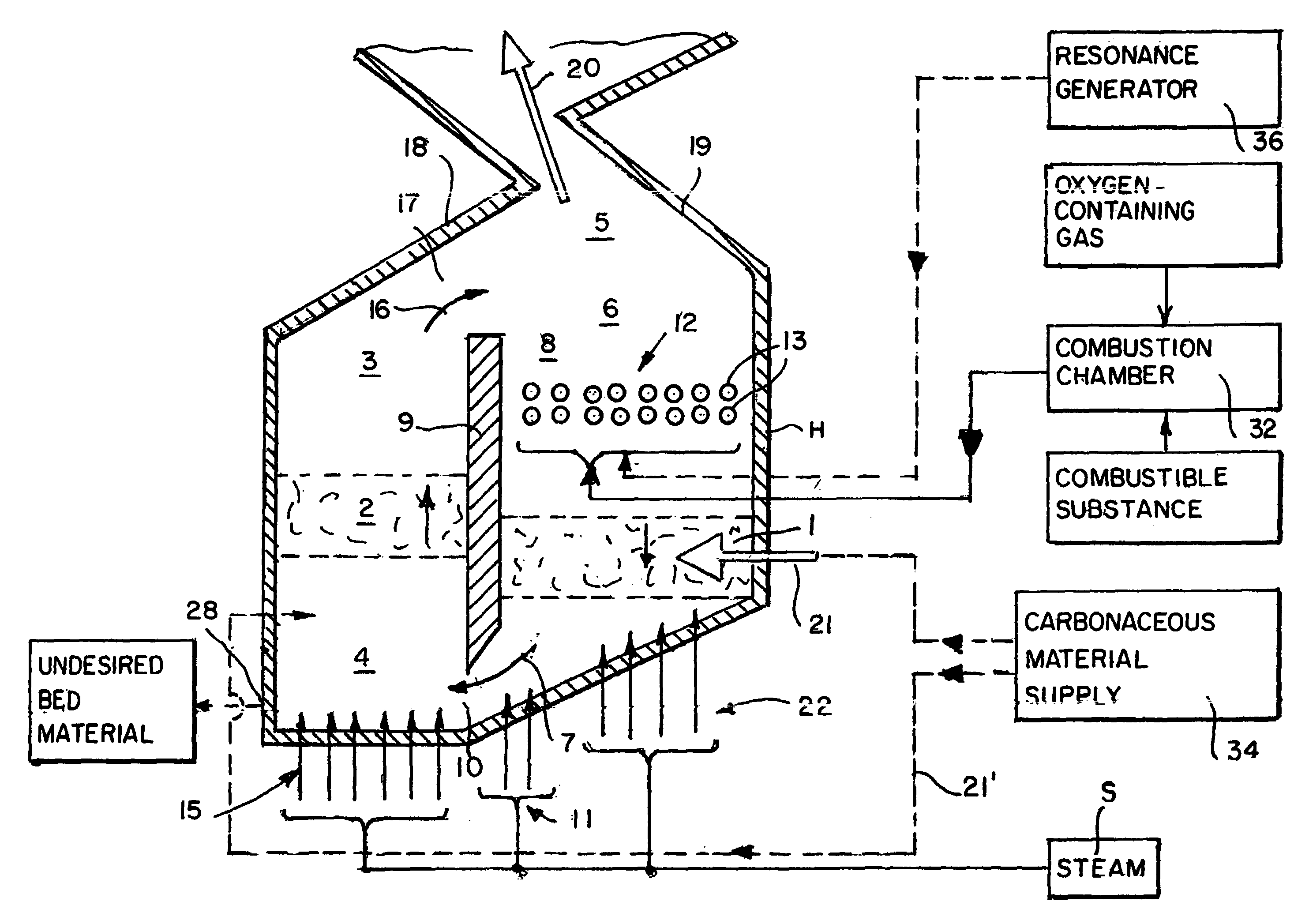
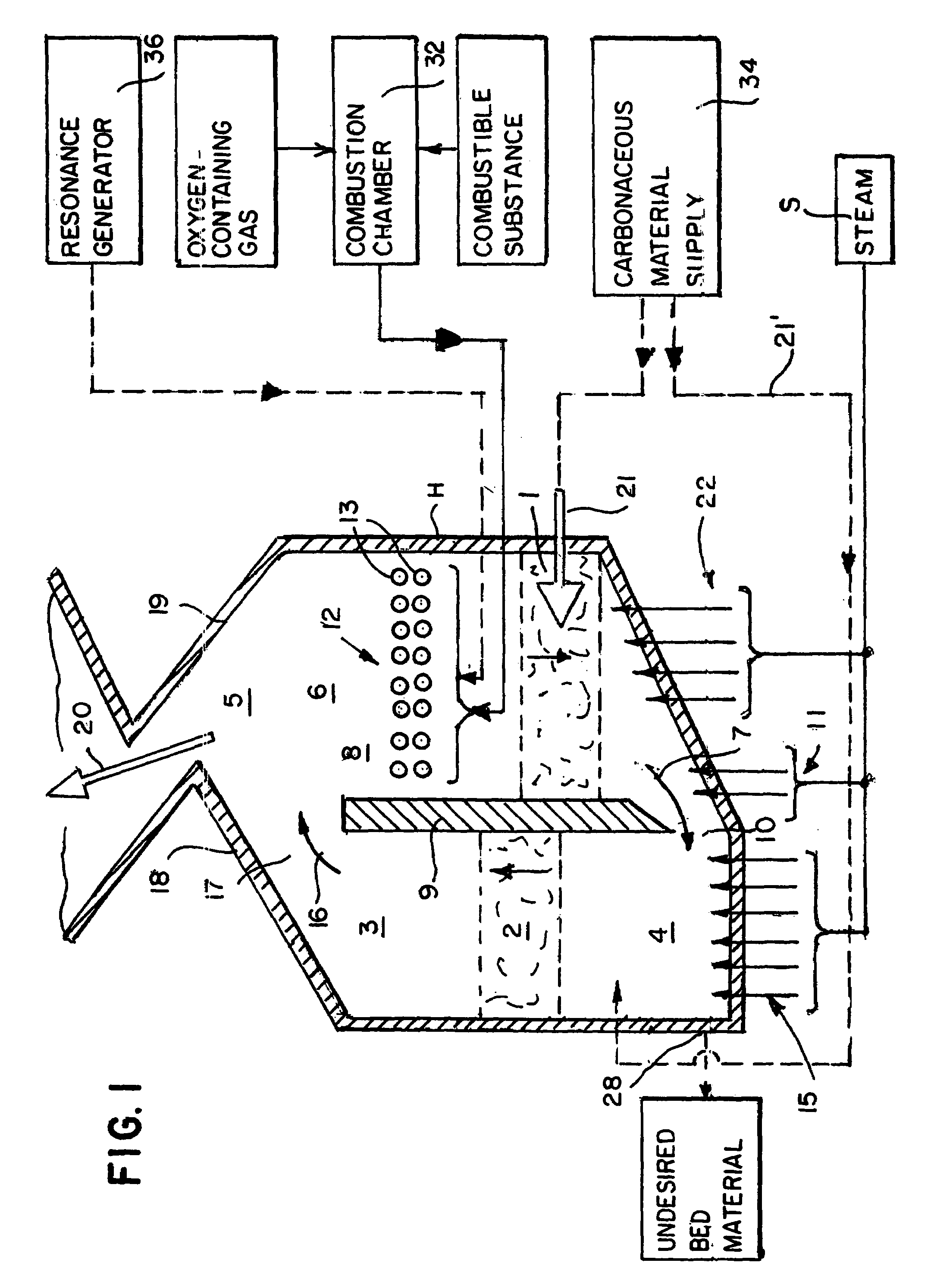
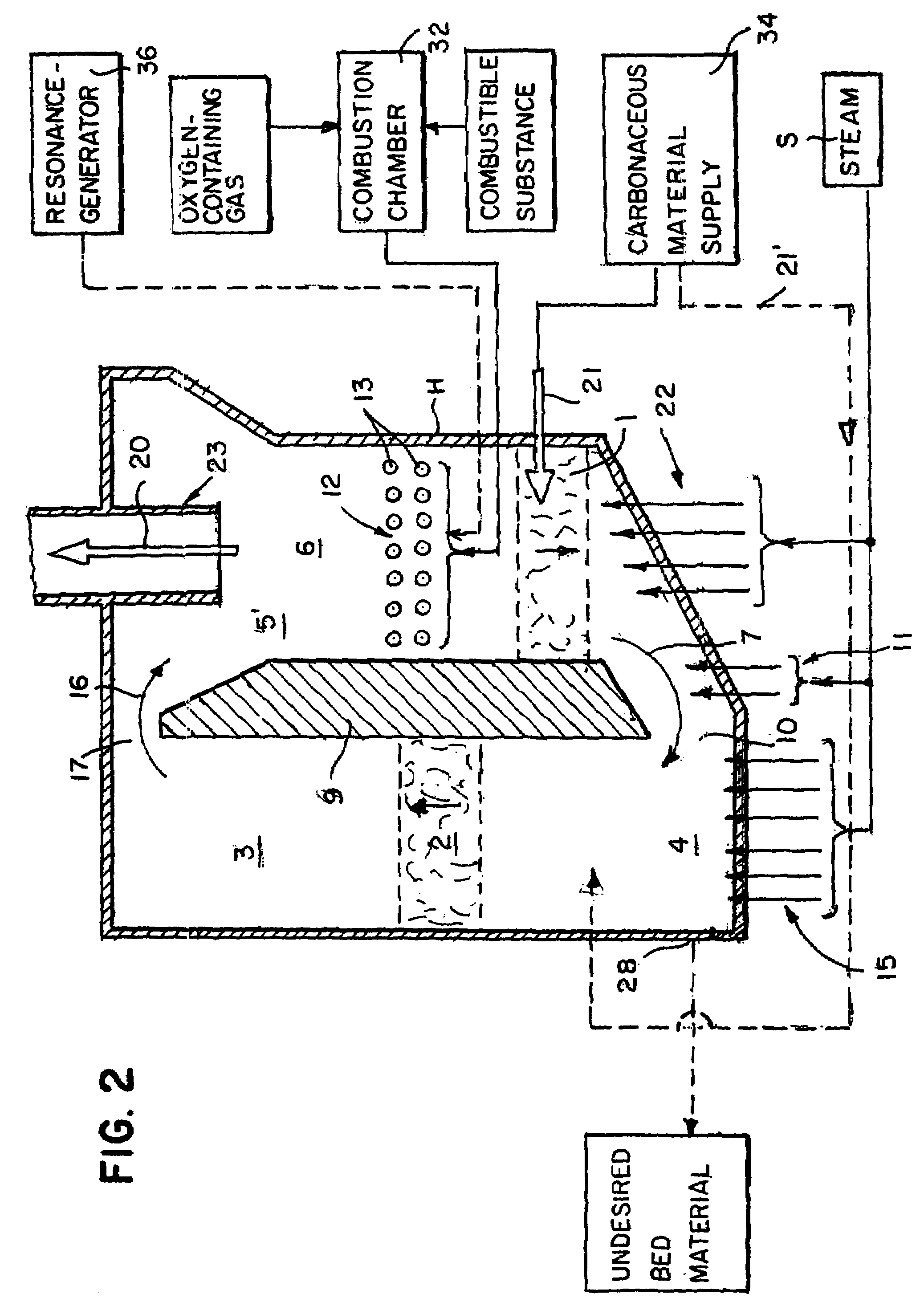
[0037]The embodiment of the apparatus of the invention as shown in FIG. 1 comprises a housing H having a chamber containing a reaction zone 3 in which carbonaceous materials are gasified. The carbonaceous materials are positioned in an ascending fluidized bed 2 which is produced with the help of fluidizing means 4 in the reaction zone 3. The fluidizing means 4 provided in the lower area of the reaction zone 3 may, e.g., be an open or closed first nozzle bottom 15 through which the fluidizing medium steam S is blown into the zone. The steam may be mixed with gases. The nozzle bottom 15 defines the reaction zone 3 in which the fluidized bed 2 is formed. Next to or below the nozzle bottom 15, there is provided an outlet 28 from which, e.g., bed material, undesired materials arising from the fuel, ash and non-reacted fuel components can be withdrawn. Steam may be injected into the outlet, said steam facilitating a withdrawal on the one hand and ensuring a post-reaction of remaining cons...


PUM


Abstract

The present invention relates to a method for obtaining combustion gases of high calorific value, wherein carbonaceous materials are allothermically gasified in a fluidized layer containing solid particles, using a gaseous gasifying agent and by supply of heat, and the gases thus produced are separated from the solid particles and withdrawn. Said method is characterized in that the solid particles are indirectly heated in a first descending bed and supplied to a second ascending fluidized bed in which the fluidized layer is formed and gasification takes place for the greatest part. The method further relates to an apparatus for performing said method.

Description

REFERENCE TO RELATED APPLICATION[0001]This application is a continuation application of PCT International Application No. PCT / EP00 / 09767 filed Oct. 5, 2000, which is based on the German Application No. 199 48 332.9 filed Oct. 7, 1999. It is also a continuation of U.S. application Ser. No. 10 / 116,038 filed Apr. 5, 2002, now abandoned.BACKGROUND OF The INVENTIONField of the Invention[0002]The present invention relates to a method for obtaining combustion gases of high calorific value and to an apparatus for performing the method.[0003]Careful use of resources becomes more and more the central objective of society. Energy generation from waste materials and regenerative substances such as biogenic fuels during first or consecutive use is thus of special importance. Furthermore, towards the end of the 20th century the generation of hydrogen becomes more and more the center of interest, not least due to the beginning exploitation of hydrogen in fuel cells.[0004]The energetic exploitation...

Claims


Application Information

Patent Timeline
IPC IPC(8): C01B3/32C10J3/48C10J3/56
CPCC10J3/482C10J3/56C10J2300/1261C10J2300/0973C10J2300/1246C10J2200/09
Inventor STEER, THOMAS
Owner STEER THOMAS
Learn More