Process and device for gluing dried fibers designated for the production of fiberboards

a technology of dried fibers and gluing devices, which is applied in the direction of lignocellulosic moulding material treatment, gas current separation, reed/straw treatment, etc., can solve the problems of loss of reactivity of glue during the drying process of fibers, relatively high glue consumption of the gluing system, and increased glue consumption

Inactive Publication Date: 2006-08-22
FLAKEBOARD
View PDF12 Cites 7 Cited by
  • Summary
  • Abstract
  • Description
  • Claims
  • Application Information

AI Technical Summary

Benefits of technology

[0053]All of the devices in accordance with the invention can also be designed in a similar manner such that the fibers are supplied at the lower end of the chute section and

Problems solved by technology

However, one considerable disadvantage of the blow-line gluing system is the relatively high glue consumption (cf. e.g.: Buchholzer, P., “Leimverlusten auf der Spur” [on the track of glue losses], pages 22–24, MDF-Magazin 1999).
The increased glue consumption is caused by virtue of the fact that a part of the reactivity of the glue during the process of drying the fibers is lost by reason of the high temperatures.
Therefore, in the dryer system the emission of formaldehyde, which originates from the glue, is considerable, whereby it is necessary to implement a costly process of minimizing pollutants.
A further disadvantage of the blow-line gluing system is that the fibers which are glued in this manner have a low level of cold-stickiness due to the pre-curing in the dryer, so that after preliminary pressing a fiber mat which is formed from the fibers has a high spring-back tendency.
During compaction of the fiber mat, this can cause the fiber mat structure to be destroyed by reason

Method used


Image

  • Process and device for gluing dried fibers designated for the production of fiberboards
  • Process and device for gluing dried fibers designated for the production of fiberboards
  • Process and device for gluing dried fibers designated for the production of fiberboards

Examples


Embodiment Construction

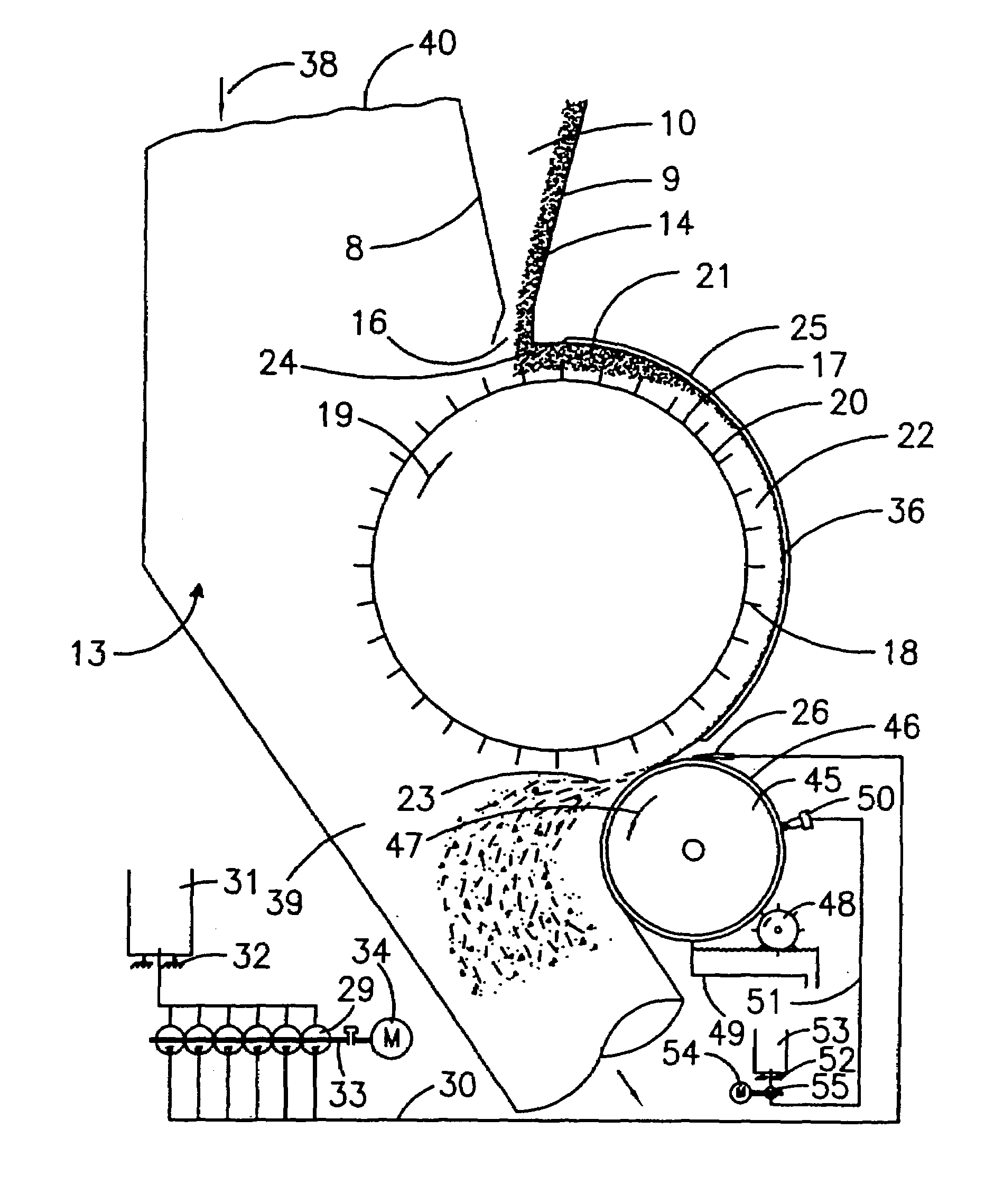
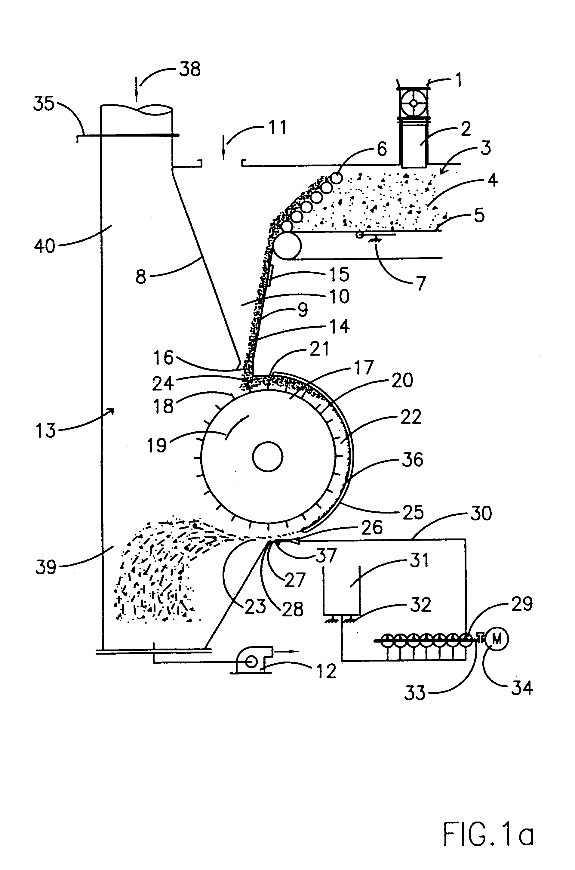
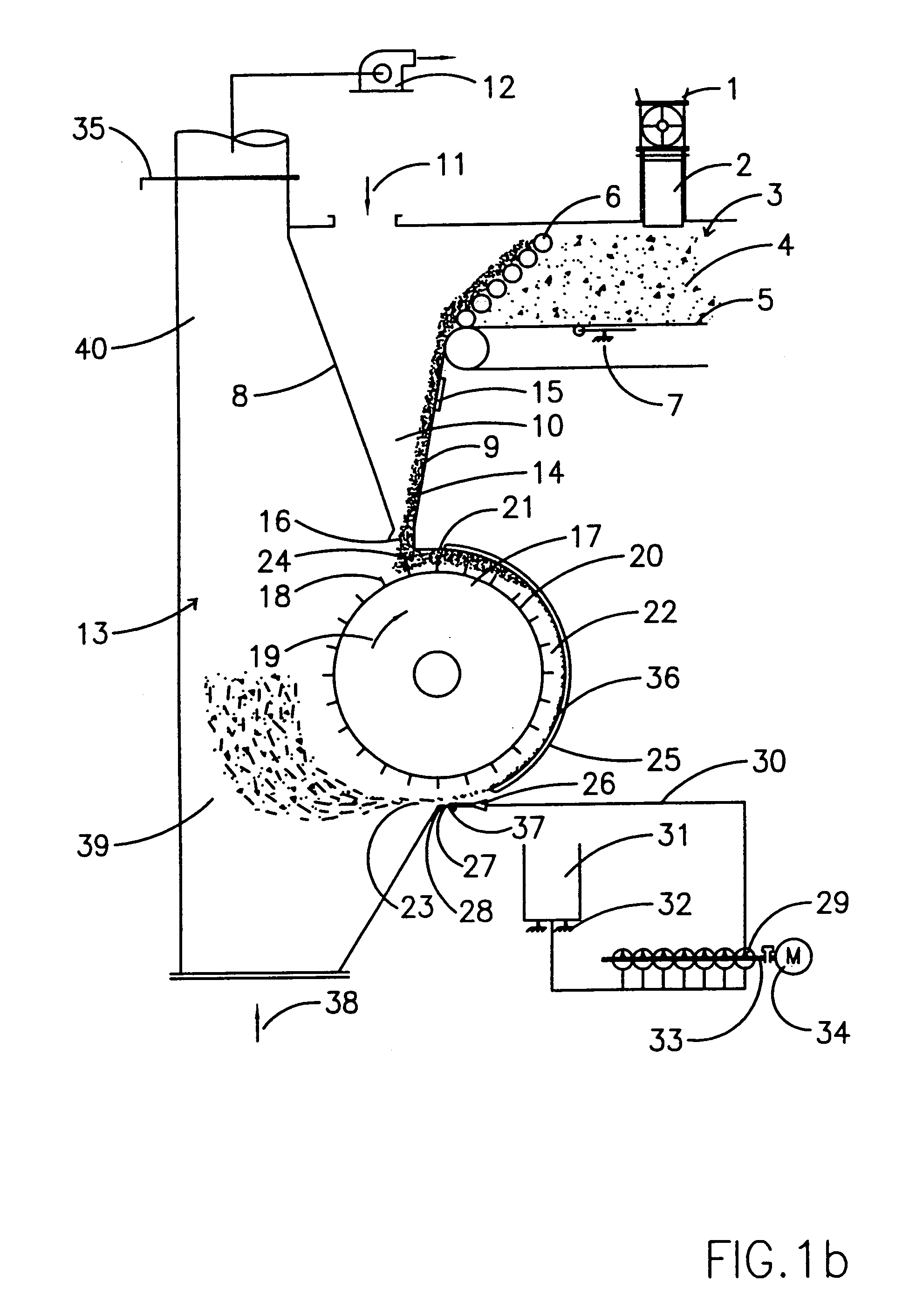
[0086]The gluing device as shown in FIG. 1a comprises a transverse fiber distributing device 2 which is connected to an outlet 1 of a fiber dryer [not illustrated]. Connected to the transverse distributing device 2 is a metering bin 3 which is filled uniformly with dried wood fibers 4 by means of the transverse distributing device 2. By means of a base belt 5, the wood fibers 4 are supplied to a metering bin outlet having discharge rollers 6. The discharge rollers 6 serve to eliminate any relatively large clumps of fibers 4. The base belt 5 passes via a weighing device 7 which continuously records the current fiber throughput weight (weight per unit of time).

[0087]The fibers 4 pass from the metering bin outlet into a feed chute 10 which is is configured from two forming-walls 8 and 9 and which comprises an air-supply 11 at an upper end.

[0088]By means of a fan 12 of a pneumatic conveying device 13, which in FIG. 1a is only partially illustrated having a partial section associated wit...


PUM

PropertyMeasurementUnit
Forceaaaaaaaaaa
Pressureaaaaaaaaaa
Centrifugal forceaaaaaaaaaa

Abstract

Dried fibers which are designated for the production of fiber boards are supplied to a fiber roller (17) from a metering device through a feed chute (10) which is subjected to negative pressure, which fiber roller is provided on its surface with a plurality of pins (18) and rotates in such a manner that the fibers (14) are deflected by the pins (18), are directed along a chute section (22) defined by means of a partial section (20) of the periphery of the fiber roller (17) and an opposite-lying wall (21) and gluing means and said fibers are accelerated to approximately the peripheral speed of the fiber roller (17) by means of the pins (18) and an air flow generated by said pins. The fibers (36) lie against a section of the wall and are glued in the region of or adjacent to one end of the wall section and exit at an outlet orifice (23) of the chute section (22). In the case of an alternative process, after exiting the chute section substantially horizontally the fibers are deflected in an upward or downward direction and are glued in this region by means of at least one spray nozzle.

Description

CROSS REFERENCE TO RELATED APPLICATION[0001]This application is a continuation of International Application number PCT / EP01 / 09212 filed on Aug. 9, 2001 which claims foreign priority to German patent 100 39 226.1 filed Aug. 11, 2000 and German patent 100 61 072. 2 filed Dec. 8, 2000.BACKGROUND[0002]The invention relates to processes and devices for gluing dried fibers designated for the production of fiberboards. The fibers preferably consist of lignocellulose-containing and / or cellulose-containing materials. The fiberboards are light, medium-density or high-density fiberboards.[0003]It is conventional to glue fibers, which are designated for the production of MDF- or HDF-boards, in the wet state. By means of this so-called blow-line gluing system, the binding agent is sprayed into a blowpipe, which terminates in the inlet region of the pipe drier, behind a refiner and on to the wet, still hot fibers. The fibers are then dried. The blow-line gluing system renders it possible to glue ...

Claims


Application Information

Patent Timeline
IPC IPC(8): B07B4/02B27N1/02
CPCB27N1/0272B27N1/0263
Inventor SCHNEIDER, FRITZ
Owner FLAKEBOARD
Why Eureka
Try Eureka