Method and apparatus for measurement of optical detector linearity

a linearity and optical detector technology, applied in the direction of optical radiation measurement, instruments, spectrometry/spectrophotometry/monochromators, etc., can solve the problems of significant measurement errors, adversely affecting or distorting the results produced by the calibrated radiance target technique, etc., and achieve the effect of improving accuracy

Active Publication Date: 2006-08-22
HARRIS CORP
View PDF15 Cites 1 Cited by
  • Summary
  • Abstract
  • Description
  • Claims
  • Application Information

AI Technical Summary

Benefits of technology

[0018]Accordingly, it is an object of the present invention to measure non-linearity of optical detectors with enhanced accuracy.
[0021]Still another object of the present invention is to modulate an optical source signal for measuring detector non-linearity via the position of a movable mirror modulating that signal and to sample the detector based on the mirror position to ensure sinusoidal modulation of the signal and enhanced measurement accuracy.
[0026]According to the present invention, an optical system for measuring detector non-linearity employs a monochromatic laser source that illuminates an integrating sphere with a laser signal. The integrating sphere randomizes the phase of the coherent laser signal and produces a uniform optical intensity over the sphere output aperture. The sphere output is expanded to a larger aperture via a collimator. The monochromatic incoherent optical laser signal enters an opto-mechanical modulator or interferometer, where the incident optical energy is amplitude modulated in a sinusoidal fashion by a linear mechanical mirror movement. The interferometer produces a sinusoidally changing optical flux that passes through optical band pass filters. The filters eliminate any possibility of significant harmonic content being present on the pre-detected optical signal.
[0028]The sampled electrical signals are processed to determine signal components attributed to detector / electronic non-linearity and laser signal reflection. The system utilizes at least two measurements to perform the processing. A first measurement is performed with the laser source at maximum intensity, while a second measurement is performed with the laser source at reduced intensity. An optional third measurement of a cold black body target (e.g., background radiance) may be applied to the first two measurements to enhance measurement accuracy. The sampled signals produce data that enable the signal component attributed to detector non-linearity to be identified, thereby providing a non-linearity measurement for the detector.

Problems solved by technology

The characteristics of the detectors and associated electronics may adversely affect or distort results produced by the instruments or devices.
However, the calibrated radiance target technique suffers from several disadvantages.
In particular, this technique is subject to substantial measurement errors due to black body targets reflecting optical radiance originating from the surrounding environment and the uncertainty in the black body target surface temperature.
Further, the calibrated radiance target technique typically cannot be relied upon to perform non-linearity characterization to an accuracy better than 0.5% and requires expensive deep well cavity targets with precise temperature monitoring and a test set-up designed to limit environmentally induced errors.
Moreover, this measurement technique cannot be performed fast enough to eliminate detector drift errors, while the target temperature is altered.
In addition, the calibrated radiance target technique can only characterize linearity in a static DC sense and does not provide linearity characterization as a function of detector operating frequency.
In particular, this technique incurs measurement errors due to the sources heating the integrating sphere and altering sphere characteristics.
Further, the technique is not fast enough to eliminate detector drift errors in response to the source targets changing temperature and does not perform well at IR wavelengths due to the uncertainty of the integrating sphere background radiance.
Moreover, this technique can only characterize non-linearity in a static DC sense and does not provide characterization as a function of detector operating frequency.
In particular, this technique has limited performance capability due to non-linearity of the modulated optical source which is often greater than the detector undergoing characterization.
Further, the LED harmonic analysis technique has a poor signal-to-noise (S / N) ratio to resolve harmonics due to the broadband emission of LED emitters.
In particular, this technique has limited performance capability due to non-linearity of the electrically modulated optical source which is often greater than the detector undergoing characterization.
Further, the laser diode can only be successfully modulated over a small fraction of its output range, thereby introducing an unwanted optical bias for detector non-linearity characterization and a much reduced signal-to-noise ratio for making the characterization.

Method used


Image

  • Method and apparatus for measurement of optical detector linearity
  • Method and apparatus for measurement of optical detector linearity
  • Method and apparatus for measurement of optical detector linearity

Examples


Embodiment Construction

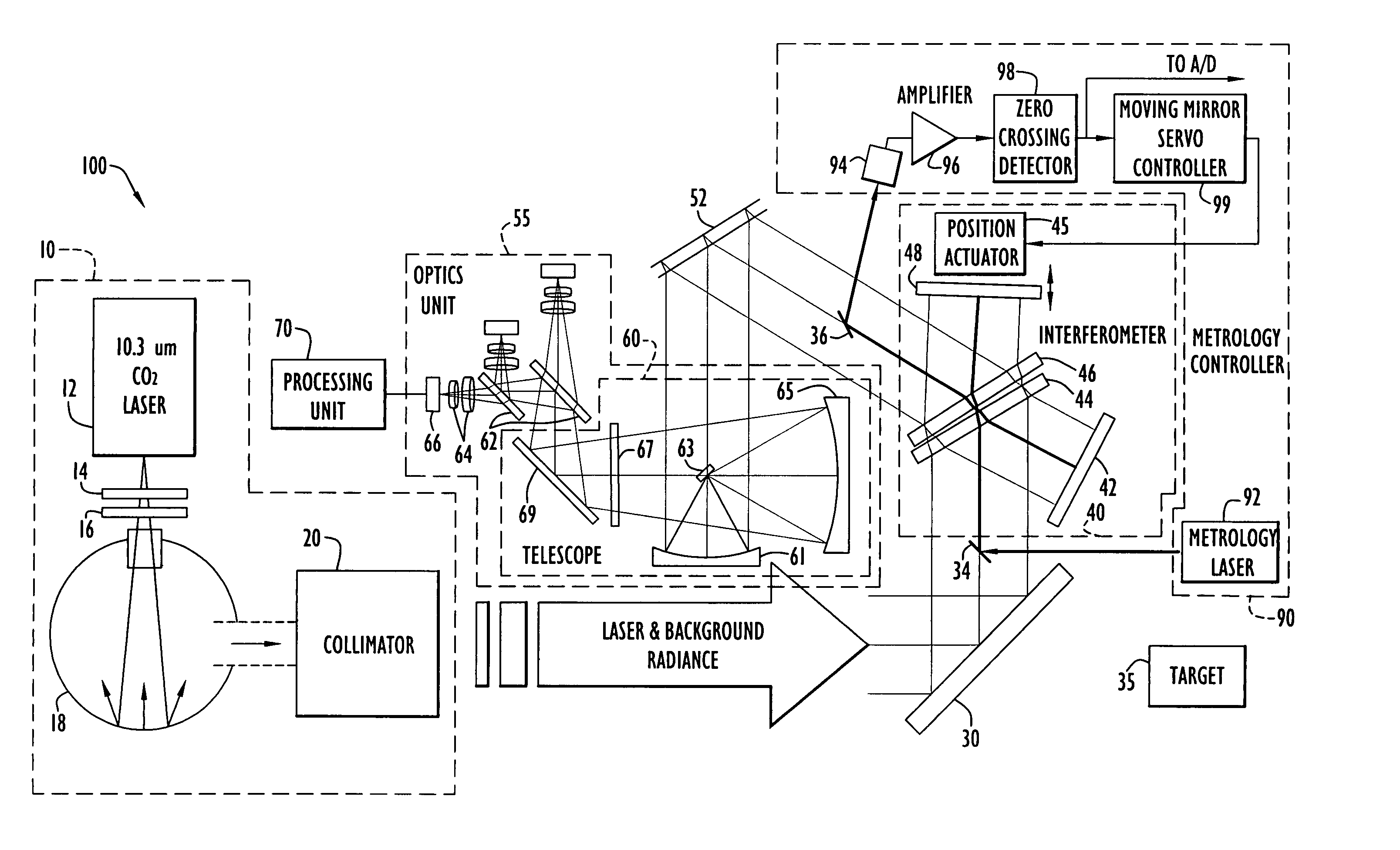
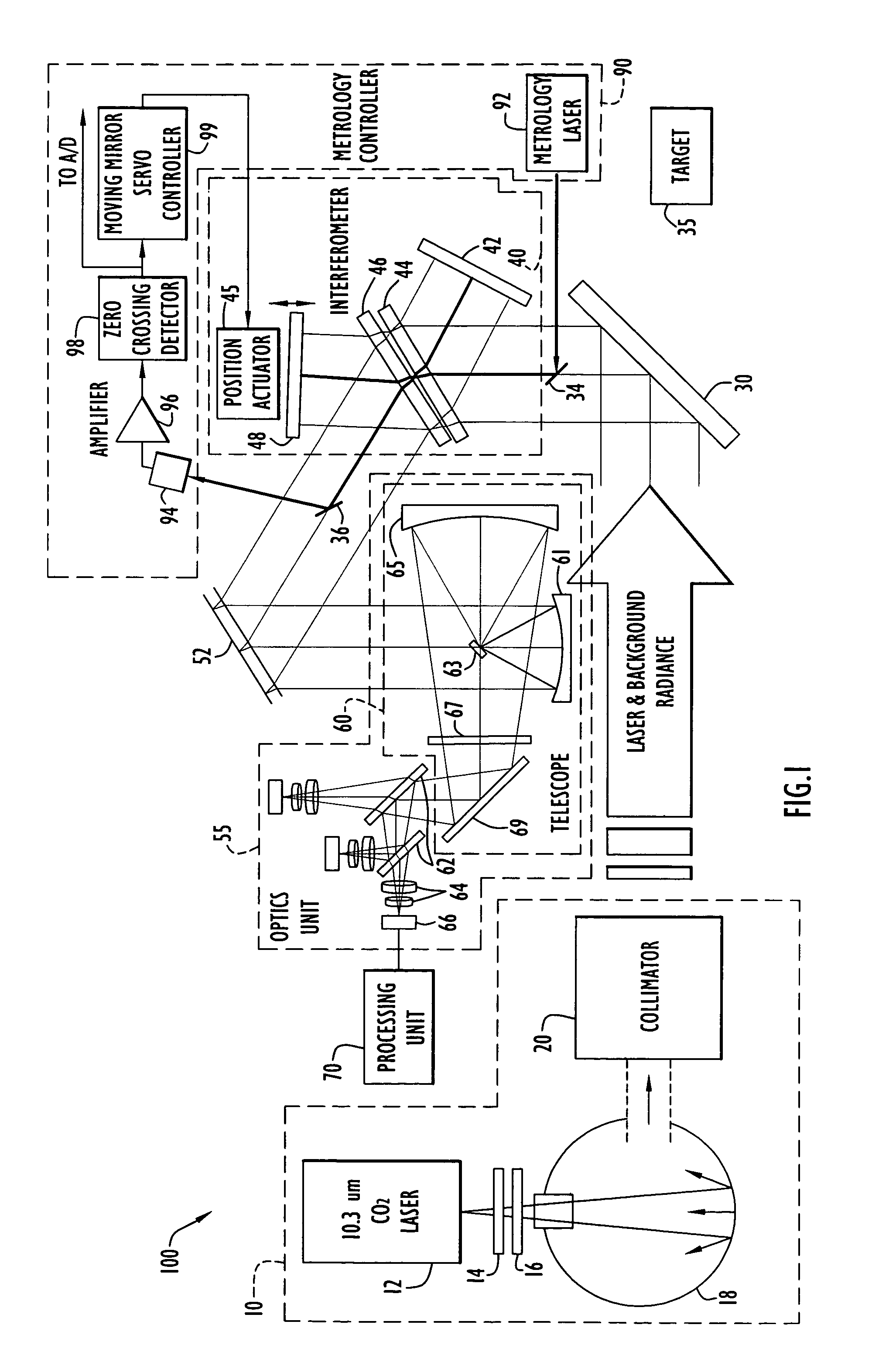
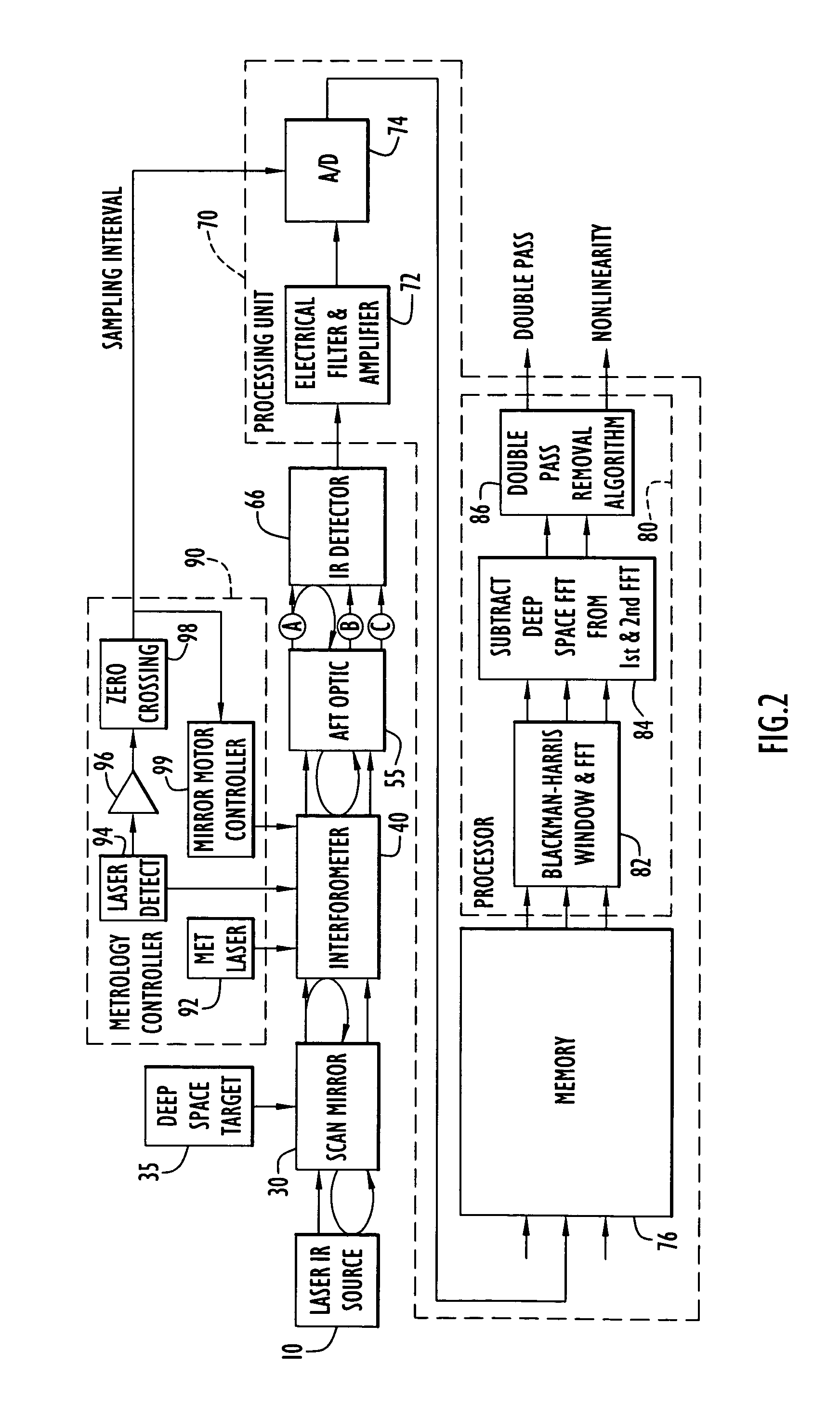
[0035]The present invention system generates optical signals for detection by a detector to determine the detector non-linearity. The generated signals are modulated and sampled in accordance with the position of a moving interferometer porchswing mirror to ensure sinusoidal modulation as described below. The sampled signal includes components respectively attributed to reflection of the signal within the optical system and / or detector non-linearity. These components are identified within the sampled signal based on a harmonic analysis, where the non-linearity component indicates the detector non-linearity as described below. The system optical arrangement and harmonic analysis enable the non-linearity measurement to be performed with enhanced accuracy.

[0036]A system 100 for measuring detector non-linearity according to the present invention is illustrated in FIGS. 1–2. Specifically, system 100 includes a laser source 10, a scene select module 30, an interferometer 40, an optics uni...


PUM


Abstract

A system for measuring optical detector linearity according to the present invention employs a laser source that illuminates an integrating sphere. The sphere randomizes the laser signal phase and produces a uniform intensity over the sphere output. A collimator expands the sphere output for entry into an interferometer, where the incident optical energy is amplitude modulated in a sinusoidal fashion by a linear mechanical mirror movement. Optical band filters eliminate significant harmonic content being present on a pre-detected optical signal. Sampling of the detected signal energy is performed synchronous to the mechanical mirror position to assure sinusoidal response. The sampled signals are processed to separately determine signal harmonic components attributed to detector non-linearity and multiple laser reflections within the system. The system utilizes at least two measurements at two different laser intensities. An optional third measurement of background radiance may be applied to the first two measurements to enhance accuracy.

Description

STATEMENT REGARDING FEDERALLY SPONSORED RESEARCH OR DEVELOPMENT[0001]The U.S. Government may have a paid-up license in this invention and the right in limited circumstances to require the patent owner to license others on reasonable terms.BACKGROUND OF THE INVENTION[0002]1. Technical Field[0003]The present invention pertains to systems for measuring properties of optical detectors. In particular, the present invention pertains to a system for measuring optical detector linearity by identifying signal portions attributed to detector non-linearity based on a harmonic analysis of measurement signals detected by the detector.[0004]2. Discussion of the Related Art[0005]Various instruments and devices employ optical detectors for operation. The characteristics of the detectors and associated electronics may adversely affect or distort results produced by the instruments or devices. Accordingly, the related art provides several techniques to measure detector characteristics, such as non-li...

Claims


Application Information

Patent Timeline
Patent Type & Authority Patents(United States)
IPC IPC(8): H01L31/00
CPCG01J1/08G01J5/522G01J3/4535G01N2201/124G01J5/53
Inventor PREDINA, JOE PAULWILLIAMS, FREDERICK LEE
Owner HARRIS CORP
Why Eureka
Try Eureka