
Multispectral multipolarization antenna-coupled infrared focal plane array

a multi-polarization, infrared technology, applied in the field of infrared detectors, can solve the problems of insufficient preference of antenna systems, polarization-resolved imagery is largely unexploited, and the spectral or polarization response of infrared systems is not known

Inactive Publication Date: 2006-08-22
UNIV OF CENT FLORIDA RES FOUND INC +1
View PDF14 Cites 43 Cited by
  • Summary
  • Abstract
  • Description
  • Claims
  • Application Information

AI Technical Summary

Benefits of technology

[0018]The fourth objective of the present invention is to provide an IR detector antenna system and method of using an antenna system where different materials are not required at each site to obtain a different spectral response.
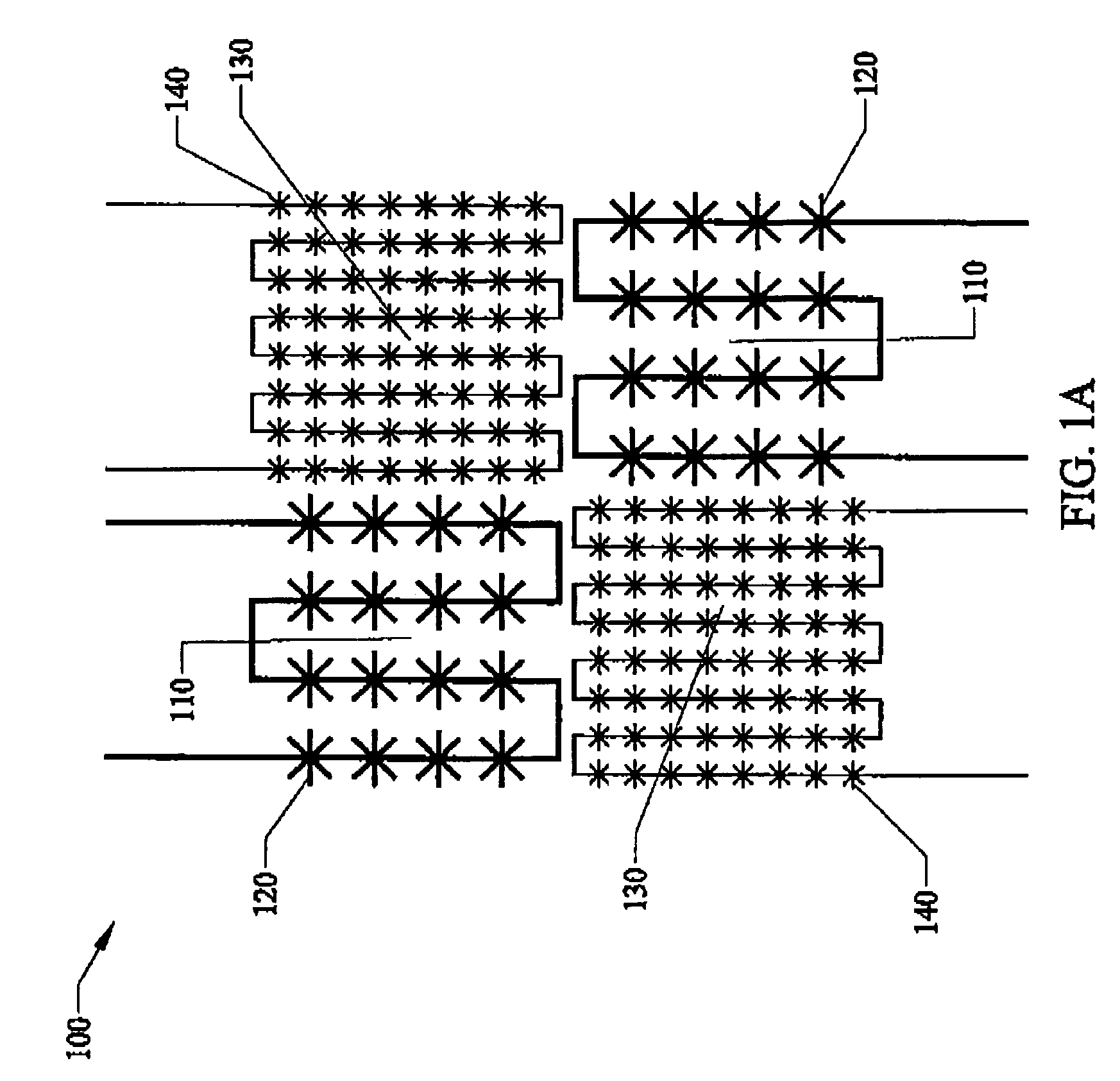
[0022]Adjacent pixels of an infrared focal plane array can be configured to have different spectral or polarization responses by adjustment of the lengths or orientations of the antenna arms which couple radiation into the sensors. The manufacturing costs of such an antenna-coupled IR FPA would be much less than integration of spectral or polarization filters onto each pixel, or fabrication of adjacent pixels with materials of different bandgaps. The antenna-coupled pixels can be made smaller than usual pixels, allowing this diversity of spectral or polarization information on the FPA without losing spatial resolution.

Problems solved by technology

A principal limitation has been the spectral or polarization response of infrared systems.
Polarization-resolved imagery is largely unexploited, because of inconvenient implementation.
Many U.S. patents have been proposed for infrared detectors but have many of the problems previously described including the preference inadequacy of the antenna systems.

Method used


Image

  • Multispectral multipolarization antenna-coupled infrared focal plane array
  • Multispectral multipolarization antenna-coupled infrared focal plane array
  • Multispectral multipolarization antenna-coupled infrared focal plane array

Examples


Embodiment Construction

[0033]Before explaining the disclosed embodiments of the present invention in detail it is to be understood that the invention is not limited in its application to the details of the particular arrangements shown since the invention is capable of other embodiments. Also, the terminology used herein is for the purpose of description and not of limitation.

[0034]This invention is related to U.S. Pat. No. 6,459,084, Issued Oct. 1, 2002, entitled “Area Receiver with Antenna Coupled IR Sensors,” by one of the inventors and assignees of the subject invention, which is incorporated by reference.

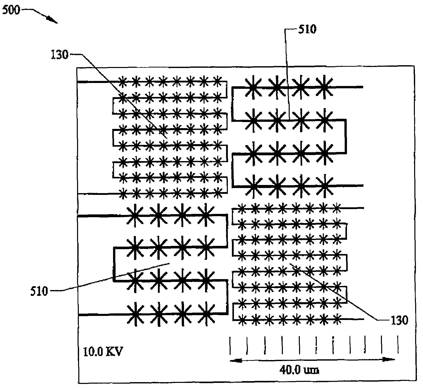
[0035]FIG. 1a is a plan view of the preferred embodiment of the Infrared Focal Plane Array 100 illustrating the arrangement of pixels on the array, with one pixel 110 composed of a matrix of IR detectors 120 responsive from approximately the 8 to approximately 12 micrometer region of infrared radiation, and the adjacent pixel 130 composed of a matrix of IR detectors 140 responsive from approximately ...


PUM


Abstract

Adjacent pixels of an infrared focal plane array (IR FPA) can be configured to have different spectral or polarization responses by adjustment of the lengths or orientations of the antenna arms which couple radiation into the sensors. The manufacturing costs of such an antenna-coupled IR FPA would be much less than integration of spectral or polarization filters onto each pixel, or fabrication of adjacent pixels with materials of different bandgaps. The antenna-coupled pixels can be made smaller than usual pixels, allowing this diversity of spectral or polarization information on the FPA without losing spatial resolution. The infrared (IR) sensors can be tunnel diodes, schottky diodes, photovoltaics, photoconductors, bolometers, and pyroelectrics. Application areas can include military and civilian remote sensing, automotive driving aids, industrial sensing, medical imaging, and general surveillance.

Description

FIELD OF USE[0001]This invention relates to the field of infrared detectors, and in particular to an infrared focal plane arrays and methods of using the arrays that can be configured to have different spectral or polarization responses by adjusting lengths or orientations of the antenna arms that couple radiation into the sensors.BACKGROUND AND PRIOR ART[0002]Infrared (IR) systems have been widely used in the past. A conventional system has an array of large-area detectors wherein each detector corresponds to a single picture element (pixel) for an image. Each detector is a planar structure that has both the length and width dimensions larger than the wavelength of the incident radiation such that the detector has adequate collection area for the incident radiation.[0003]A principal limitation has been the spectral or polarization response of infrared systems. Typically, an infrared detector is responsive to only a small region of infrared radiation or to the entire band of infrare...

Claims


Application Information

Patent Timeline
Patent Type & Authority Patents(United States)
IPC IPC(8): G01J5/20
CPCG01J5/08G01J4/04G01J5/10G01J5/0837
Inventor BOREMAN, GLENN D.GONZALEZ, FRANCISCO J.PORTER, JAMES L.
Owner UNIV OF CENT FLORIDA RES FOUND INC
Learn More