Multi-slice flat panel computed tomography

a computed tomography and multi-slice technology, applied in the field of image acquisition systems and methods, can solve the problems of limiting the rotation rate of the gantry, reducing accumulating relative massive amounts of data, so as to reduce the time it takes to readout signals from all lines of the detector elements in the detector, and improve the frame rate of the detector

Active Publication Date: 2006-08-22
VAREX IMAGING CORP
View PDF64 Cites 32 Cited by
  • Summary
  • Abstract
  • Description
  • Claims
  • Application Information

AI Technical Summary

Benefits of technology

[0008]In accordance with some embodiments of the invention, a radiation projection detector for generating signals in response to a radiation beam is provided. The detector has a first imager that includes a conversion layer configured to generate light photons in response to a radiation, a photo detector array aligned with the conversion panel, the photo detector array having a plurality of lines of detector elements, and an access circuit coupled to the photo detector array and configured to collect signals from two or more of the lines of detector elements simultaneously. By collecting signals from two or more lines of detector elements simultaneously or in parallel, the time it takes to readout signals from all lines of the detector elements in the detector can be reduced. This in turn, improves a frame rate of the detector. In some embodiments, the radiation projection detector includes a second imager. In such cases, the access circuit is configured to collect signals from the first imager and the second imager simultaneously. The plurality of the imagers provides another level of multiplexing in that signals from one or more lines of detector elements in the first imager can be read simultaneously with signals from one or more lines of detector elements in the second imager.
[0009]In accordance with other embodiments of the invention, a radiation projection detector for generating signals in response to a radiation beam is provided. The detector has a first imager that includes a photoconductor layer configured to generate a charge in response to a radiation, a detector array aligned with the photoconductor layer, the detector array having a plurality of lines of detector elements, and an access circuit coupled to the detector array and configured to collect signals from two or more of the lines of detector elements simultaneously. By collecting signals from two or more lines of detector elements simultaneously or in parallel, the time it takes to readout signals from all lines of the detector elements in the detector can be reduced. This in turn, improves a frame rate of the detector. In some embodiments, the radiation projection detector includes a second imager. In such cases, the access circuit is configured to collect signals from the first imager and the second imager simultaneously. The plurality of the imagers provides another level of multiplexing in that signals from one or more lines of detector elements in the first imager can be read simultaneously with signals from one or more lines of detector elements in the second imager.

Problems solved by technology

By taking thousands of readings from multiple angles around the patient, relatively massive amounts of data are thus accumulated.
A problem associated with existing CT imaging systems is that a patient may not feel comfortable confined within a gantry opening, especially when the image data collection procedure takes too long.
Mechanical configuration and / or regulatory rules may limit the rotation rate of a gantry on which the x-ray source and the image detector are mounted.
Some of the existing CT imaging devices have gantry speed that is limited to one rotation per minute.
Although some of the existing CT scanners can be configured to rotate about a patient faster, the volumetric data set generated from such scanners may have motion artifacts between slices.
Another problem associated with existing CT imaging systems is that a slice thickness is generally larger than a resolution of a pixel within a slice.
However, increasing the number of detectors in the Z-axis increases the manufacturing cost of the detector, which is already quite expensive as it is based on traditional single crystal silicon electronics coupled to x-ray converters.

Method used


Image

  • Multi-slice flat panel computed tomography
  • Multi-slice flat panel computed tomography
  • Multi-slice flat panel computed tomography

Examples


Embodiment Construction

[0020]Various embodiments of the present invention are described hereinafter with reference to the figures. It should be noted that the figures are not drawn to scale and elements of similar structures or functions are represented by like reference numerals throughout the figures. It should also be noted that the figures are only intended to facilitate the description of specific embodiments of the invention. They are not intended as an exhaustive description of the invention or as a limitation on the scope of the invention. In addition, an aspect described in conjunction with a particular embodiment of the present invention is not necessarily limited to that embodiment and can be practiced in any other embodiments of the present invention.

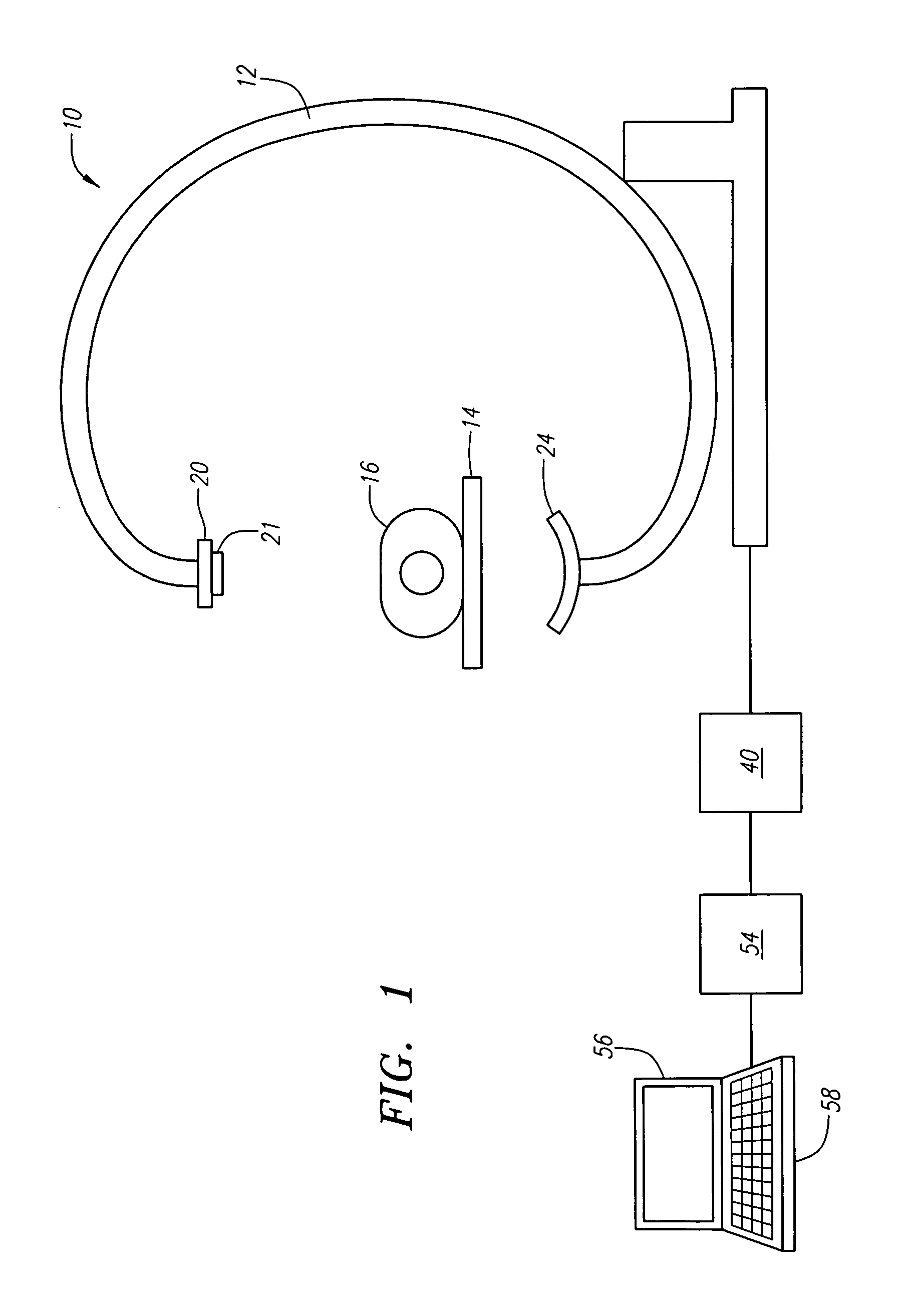
[0021]Referring now to the drawings, in which similar or corresponding parts are identified with the same reference numeral, FIG. 1 illustrates a computed tomography (CT) image acquisition system 10, which includes a detector 24 constructed in acc...


PUM


Abstract

A method for collecting signals from a detector that has a plurality of lines of image elements includes sending a control signal to a gate driver to select transistor gates for two or more lines of image elements, and simultaneously passing signals from the two or more lines of image elements to charge amplifiers that are coupled to the image elements. A method for collecting signals from a detector that has a plurality of imagers is provided. Each of the imagers has a plurality of lines of image elements. The method includes sending a control signal to a gate driver to select one or more lines of image elements on each of the plurality of the imagers, and simultaneously passing signals from the selected one or more lines of image elements on each of the plurality of the imagers to charge amplifiers that are coupled to the image elements.

Description

BACKGROUND OF THE INVENTION[0001]1. Field of the Invention[0002]This invention relates generally to systems and methods for image acquisition and, more specifically, to systems and methods for collecting computed tomography (CT) image data.[0003]2. Background of the Invention[0004]Computed tomography is an imaging technique that has been widely used in the medical field. In a procedure for computed tomography, an x-ray source and a detector apparatus are positioned on opposite sides of a portion of a patient under examination. The x-ray source generates and directs a x-ray beam towards the patient, while the detector apparatus measures the x-ray absorption at a plurality of transmission paths defined by the x-ray beam during the process. The detector apparatus produces a voltage proportional to the intensity of incident x-rays, and the voltage is read and digitized for subsequent processing in a computer. By taking thousands of readings from multiple angles around the patient, relat...

Claims


Application Information

Patent Timeline
Patent Type & Authority Patents(United States)
IPC IPC(8): G21K1/12A61B
CPCA61B6/032A61B6/4233A61B6/4411A61B6/4441H04N5/378G01T1/2018H04N5/32H04N5/374A61B6/5205A61B6/025H04N25/76H04N25/75G01T1/20184G01T1/20182
Inventor MOLLOV, IVANCOLBETH, RICHARD E.
Owner VAREX IMAGING CORP
Why Eureka
Try Eureka