

Embolic protection systems
- Summary
- Abstract
- Description
- Claims
- Application Information
AI Technical Summary
Benefits of technology
Problems solved by technology
Method used
Image

Examples
first embodiment
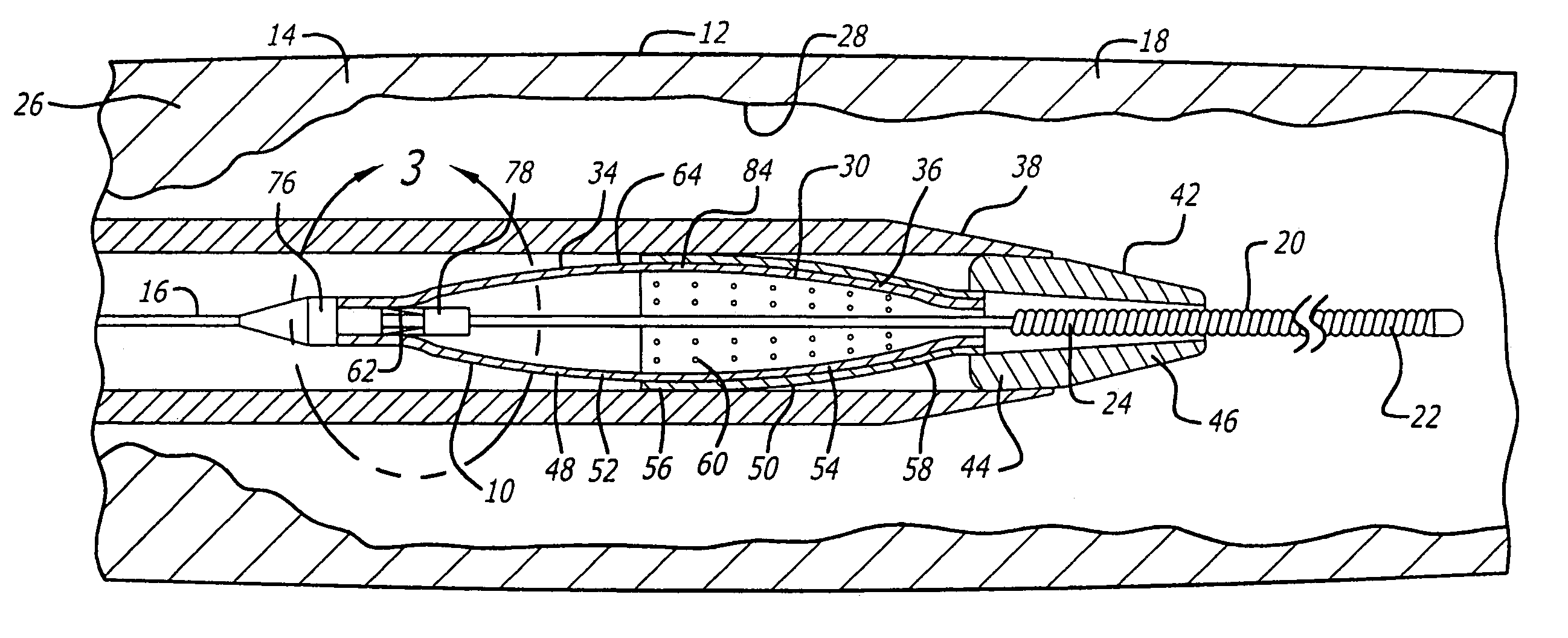
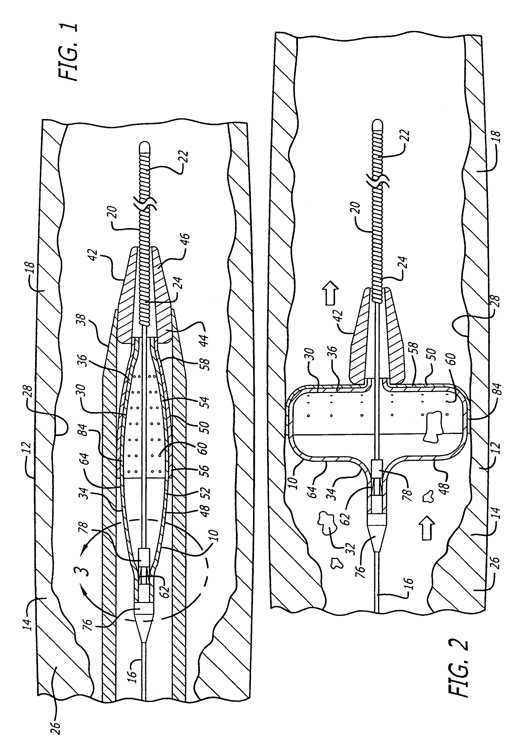
[0058]Referring to FIGS. 1–21, in a system pursuant to the present invention, for example, the system 10 enables movement thereof through the patient's blood vessel 12 to a position distal to the area of treatment 14 for deployment of the filter device 30. The system 10 further enables expansion of the filter device 30 against the inside wall 28 of the blood vessel 12 and the sealing off of the inside wall 28, to enable the capture of embolic material 32 which may be released into the blood vessel 12 during the therapeutic interventional procedure.
[0059]The system 10 in accordance with the first embodiment of the invention includes the guide wire 16, positionable within the blood vessel 12, and extendable to a position distal to the interventional procedure site 14. The system 10 further includes the filter device 30, which is snap-fitted for engagement with the distal end 22 of the guide wire 16. The filter device 30 extends within a delivery sheath 38 for delivery to the intervent...
second embodiment
[0070]Referring to FIGS. 22–29, in a second embodiment in accordance with the invention, for example, a system 100 is provided for enabling expandable material 102 to be formed into an expanded configuration of a cage 104, which is a version of the cage 48. The system 100 enables forming a cage 104 for a filter device to be formed thereby, for capturing embolic material which may be released into a blood vessel during a therapeutic interventional procedure. The system 100 enables the expanded configuration of the cage 104 to provide a substantially uniform pre-formed maximum outer diameter thereof, for maintaining vessel wall opposition in a patient's vasculature upon deployment of the cage 104 at a location distal to an interventional procedure site. The expandable material 102 for forming the expanded configuration of the cage 104 is in the form of a hypotube.
[0071]In the second embodiment pursuant to the present invention, as seen in particular in FIGS. 22–26, the system 100 incl...
PUM
| Property | Measurement | Unit |
|---|---|---|
| Length | aaaaa | aaaaa |
| Shape | aaaaa | aaaaa |
Abstract
Description
Claims
Application Information