Source arc chamber for ion implanter having repeller electrode mounted to external insulator

a technology ion implants, which is applied in the field of ion beam tubes, can solve the problems of adversely affecting the efficiency of the source during operation, and achieve the effect of reducing fractionation and therefore source efficiency

Active Publication Date: 2006-09-05
VARIAN SEMICON EQUIP ASSOC INC
View PDF6 Cites 12 Cited by
  • Summary
  • Abstract
  • Description
  • Claims
  • Application Information

AI Technical Summary

Benefits of technology

[0007]A repeller mounting configuration such as described above may adversely affect the efficiency of the source during operation. The repeller retaining arm and associated structure act

Problems solved by technology

A repeller mounting configuration such as described above may adversely affect the efficiency of the source during operatio

Method used


Image

  • Source arc chamber for ion implanter having repeller electrode mounted to external insulator
  • Source arc chamber for ion implanter having repeller electrode mounted to external insulator
  • Source arc chamber for ion implanter having repeller electrode mounted to external insulator

Examples


Embodiment Construction

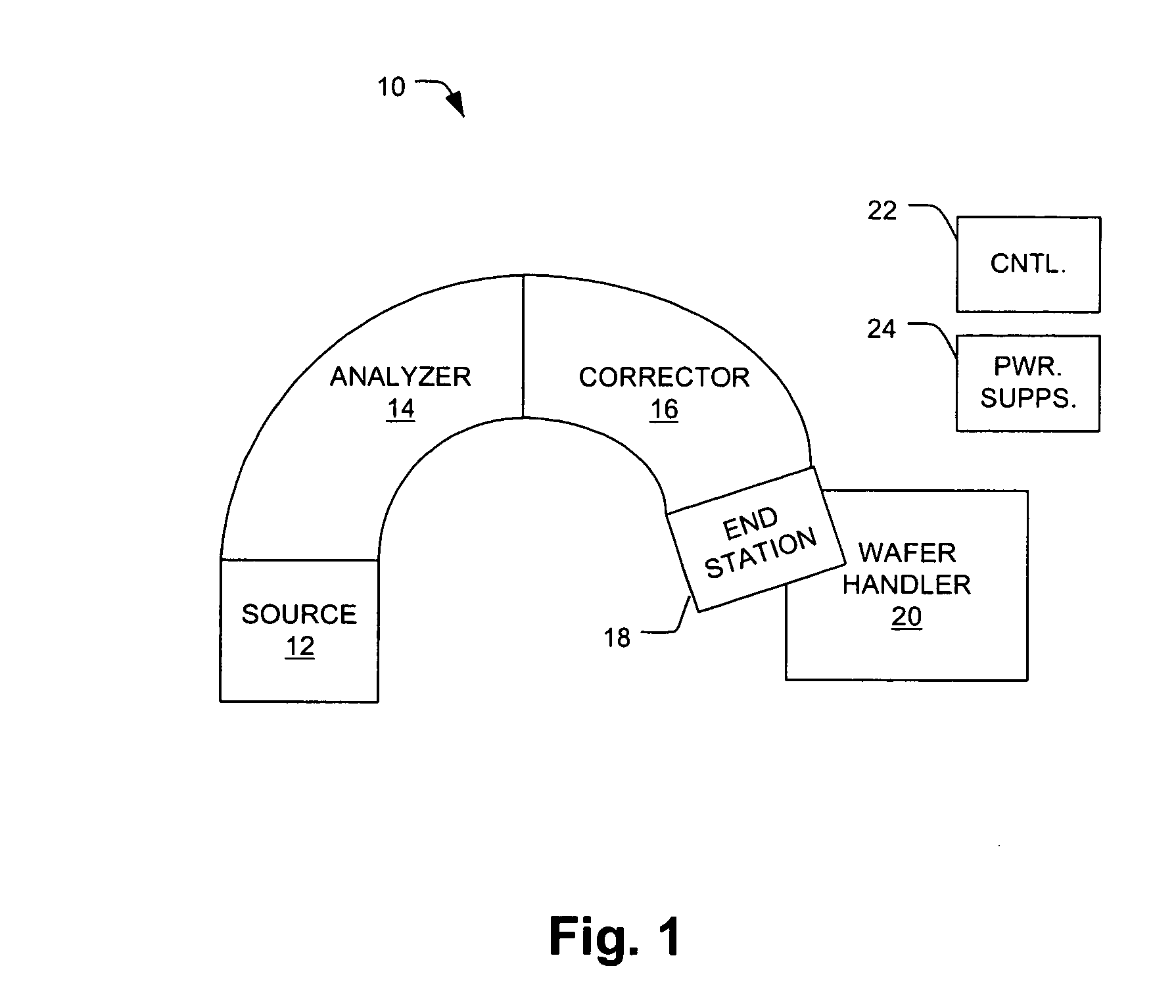
[0016]FIG. 1 shows an ion implanter 10 including a source module 12, analyzer module 14, corrector (CORR) module 16, and end station 18. Immediately adjacent to the end station 18 is a wafer handler 20. Also included are control circuitry (CNTL) 22 and power supplies (PWR SUPPS) 24, which although shown in respective blocks in FIG. 1 are actually distributed throughout the ion implanter 10 as known to those in the art.

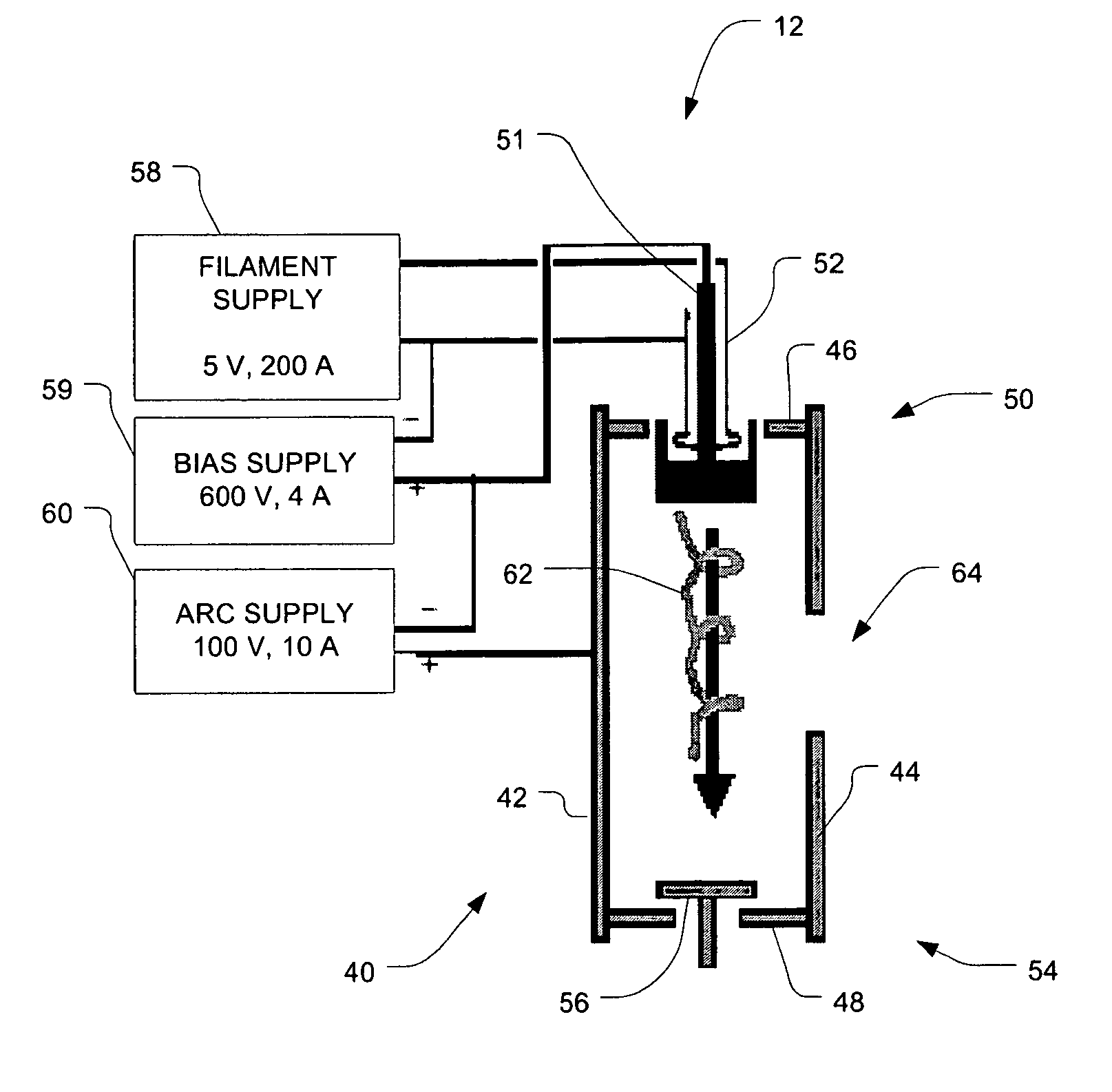
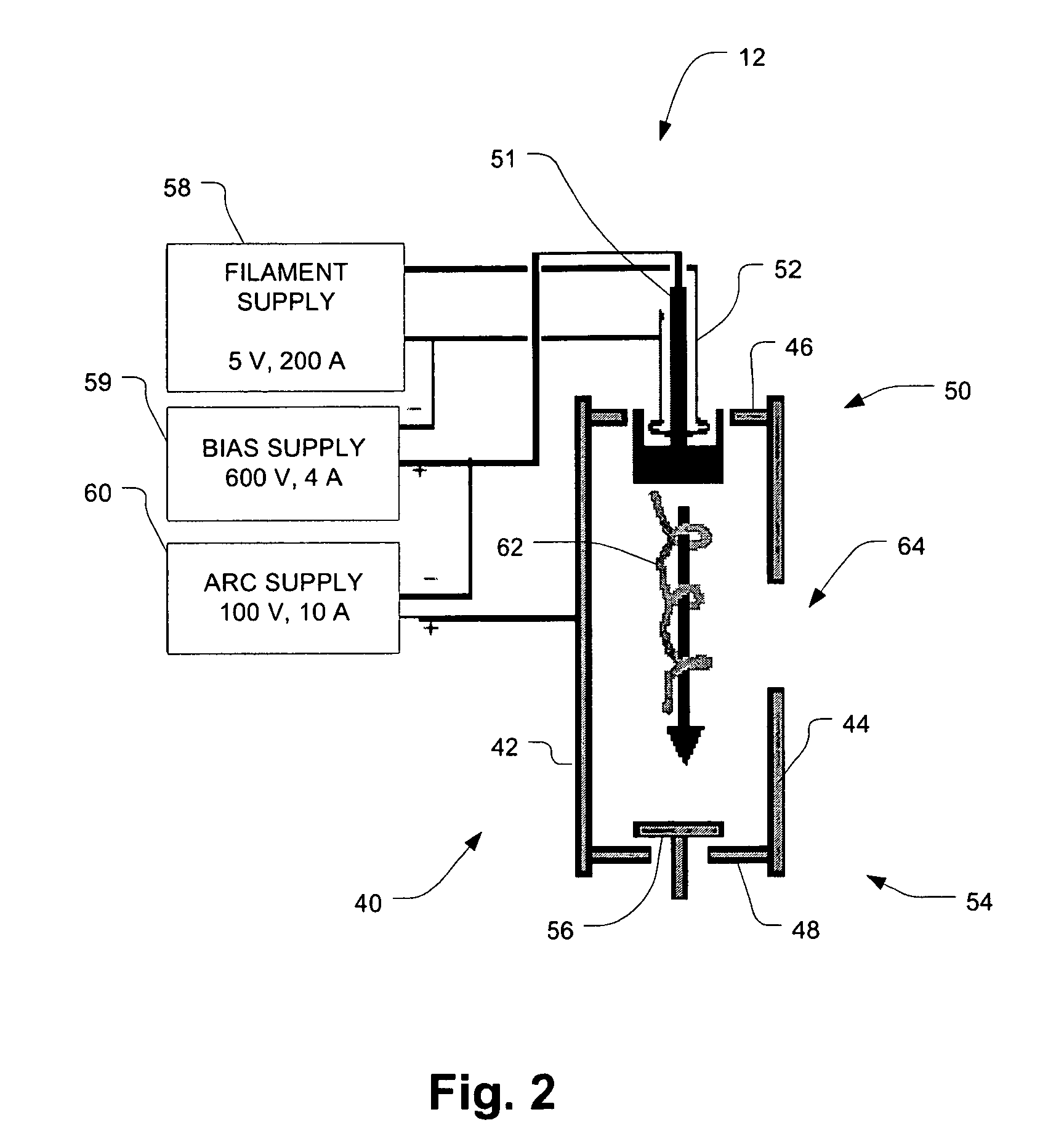
[0017]During an implantation operation, the source module 12 is fed with a gaseous compound including the element(s) to be implanted into a semiconductor wafer. As an example, for the implantation of boron (B), gaseous boron fluoride (BF3) is supplied to the source module 12. The source module 12 employs electrical excitation to form a plasma that generally includes a number of ion species resulting from fractionation of the source compound, including the desired species (e.g., B+) that is to be implanted. As the source module 12 is biased to a relatively positive pote...


PUM


Abstract

An ion implanter has a source arc chamber including a conductive end wall at a repeller end of the arc chamber, the end wall having a central portion surrounding an opening. A ceramic insulator is secured to an outer surface of the end wall, such as by peripheral screw threads engaging mating threads at the periphery of a recessed area of the end wall. A conductive repeller has a narrow shaft secured to the insulator and extending through the end wall opening, and a body disposed within the source arc chamber adjacent to the end wall. The end wall, insulator and repeller are configured to form a continuous vacuum gap between the central portion of the end wall and (i) the repeller body, (ii) the repeller shaft, and (iii) the insulator. The insulator interior surface can have a ridged cross section.

Description

BACKGROUND[0001]The present invention is related to the field of ion implanters for use in semiconductor manufacturing.[0002]Ion implanters used in semiconductor manufacturing include a source arc chamber in which an electrical discharge interacts with a gas to create a plasma containing a variety of ion species, including a desired species to be implanted in the surface of a semiconductor wafer. The positive ions are extracted from the source arc chamber in a known manner, and apparatus within the implanter separates the desired species from the undesired species and directs the desired species to the surface of the wafer at a desired energy level.[0003]In one common configuration, the source arc chamber includes an emitter electrode at one end and a repeller electrode at the other end. The emitter electrode may be a cathode heated by a filament, or simply a bare filament, and its purpose is to emit electrons by thermionic emission during operation. The electrons are accelerated in...

Claims


Application Information

Patent Timeline
IPC IPC(8): H01J7/24
CPCH01J27/08
Inventor LOW, RUSSELL J.COBB, ERIC R.OLSON, JOSEPH C.KLOS, LEO V.
Owner VARIAN SEMICON EQUIP ASSOC INC
Why Eureka
Try Eureka