Amplifier arrangement and control loop having the amplifier arrangement

a control loop and amplifier technology, applied in the direction of instruments, electric/magnetic computing, computation using denominational number representation, etc., can solve the problems of large changes in the gain factor selection, the multiplier has to be reversed within a very wide range, and the power requirement is high, so as to achieve the effect of minor effects and low power requirements

Inactive Publication Date: 2006-09-05
INTEL CORP
View PDF3 Cites 8 Cited by
  • Summary
  • Abstract
  • Description
  • Claims
  • Application Information

AI Technical Summary

Benefits of technology

[0010]An amplifier arrangement, which is of single-stage construction, is disclosed and affords a high dynamic response. In addition, the amplifier arrangement has a gain factor that can be set in a stable manner and exhibits a linear characteristic curve.
[0014]The additional output makes it possible to set the gain factor of the amplifier arrangement in such a manner that, in the case of a high dynamic response, a stable gain factor in conjunction with a simultaneously voltage-linear characteristic curve of the amplifier is ensured.
[0016]Since the additional transistor always emits, at its additional output, a signal representing the present gain factor of the entire amplifier arrangement, it is additionally advantageously possible, in accordance with the proposed principle, to also compensate for temperature drift effects and also manufacturing variations and their effects on the gain factor.
[0022]The additional transistor and the further additional transistors preferably have smaller dimensions than the transistors of the first and the second differential amplifier and are accordingly of smaller size. This means that the additional transistor and the further additional transistors branch off only a very small portion of the signal current, with the result that the perturbation effects of the additional transistors on the amplifier arrangement remain relatively minor overall.
[0028]Although manufacturing fluctuations during the production of the amplifier arrangement and also temperature fluctuations may affect the properties of the controlled system, namely of the amplifier arrangement, they are compensated for using the control loop. Only offsets of the amplifier possibly remain as residual errors, it being possible, however, to make said offsets small. It is thus ensured that the gain factor is set in a stable manner irrespective of temperature and manufacturing fluctuations. In addition, the gain factor of the amplifier follows the reference variable in a linear manner within its operating range. A VGA buffer having complicated diodes as described initially is no longer required in the control loop described, with the result that an additional advantage with regard to a particularly low power requirement is afforded.

Problems solved by technology

However, this would be associated with the disadvantage of a large area occupation when embodied using integrated circuit technology in conjunction with a likewise disadvantageous high power consumption.
However, the disadvantage of the single-stage embodiment explained is that, in the case of a high dynamic response requirement, the four transistors of the two differential amplifier cells of the Gilbert multiplier have to be reversed within a very wide range.
However, in this virtually de-energized operating state, manufacturing fluctuations during the production of integrated circuits and also temperature fluctuations lead to particularly great changes in the gain factor selected.
When the gain is considered logarithmically, this disadvantageous behavior has such an effect that it is practically no longer possible to correctly set a low gain.
Yet another disadvantage of the known structure described is that the diodes in the VGA buffer have to have the same current density as the quartet of transistors of the differential amplifier cells.

Method used


Image

  • Amplifier arrangement and control loop having the amplifier arrangement
  • Amplifier arrangement and control loop having the amplifier arrangement
  • Amplifier arrangement and control loop having the amplifier arrangement

Examples


Embodiment Construction

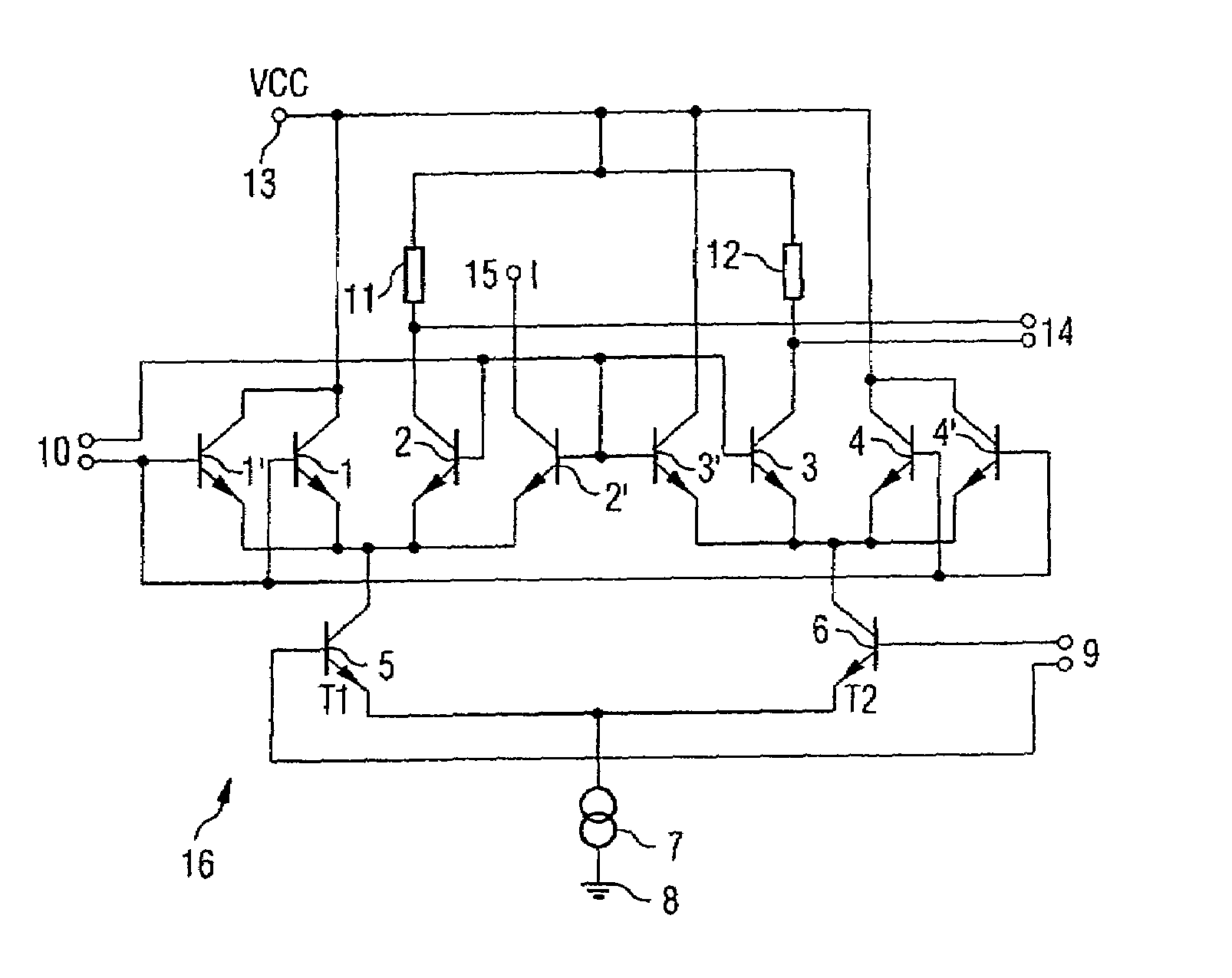
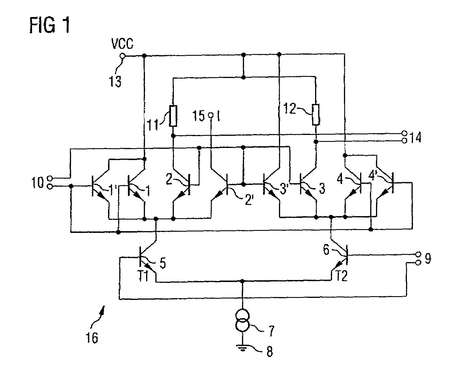
[0036]FIG. 1 shows the circuit diagram of an amplifier arrangement based on a Gilbert multiplier circuit. A first transistor and a second transistor 1, 2 are connected to one another on the emitter side and form a first differential amplifier. A second differential amplifier 3, 4 is formed by transistors 3, 4 which are likewise connected on the emitter side. The two emitter nodes are connected to respective collector terminals of further transistors 5, 6 which form a third differential amplifier. In this case, the emitter terminals of the transistors of the third differential amplifier 5, 6 are connected to one another and are connected to the reference potential 8 via a current source 7. The base terminals of the transistors 5, 6 of the third differential amplifier form the symmetrical radio frequency signal input 9 of the amplifier arrangement. A likewise symmetrical input 10 for setting the gain factor of the amplifier arrangement is formed at the base terminals of the transistor...


PUM


Abstract

An amplifier arrangement and also a control loop having the amplifier arrangement are specified, wherein the amplifier arrangement is based on a Gilbert multiplier. Connected in parallel in this case with one of the transistors of the differential amplifier cells is an additional transistor, at which it is possible to tap off a signal that is proportional to the gain factor. Processing this signal in a suitable manner, for example in a control loop, makes it possible to compensate for temperature and manufacturing fluctuations and also to obtain a highly linear characteristic curve having a gain factor which can be set in a stable manner. In addition, the structure shown is current-saving and can be used, in particular, for application in radio frequency technology as an amplifier having a variable gain factor (VGA).

Description

REFERENCE TO RELATED APPLICATIONS[0001]This application claims the benefit of the priority date of German application DE 103 33 816.0, filed on Jul. 24, 2003, the contents of which are herein incorporated by reference in their entirety.FIELD OF THE INVENTION[0002]The present invention relates to an amplifier arrangement and also to a control loop having the amplifier arrangement.BACKGROUND OF THE INVENTION[0003]In telecommunications, in particular radio frequency signal processing, the objective of generating a defined output level from a variable input level may frequently be encountered. Amplifiers having variable gain (which are also referred to as Variable Gain Amplifiers (VGA)) are normally used for this purpose.[0004]VGAs of this type may have either a dB-linear or a voltage-linear characteristic curve, the latter being distinguished by the fact that they have a gain factor which is linear with respect to a reference variable, namely a control voltage.[0005]The document by Ala...

Claims


Application Information

Patent Timeline
Patent Type & Authority Patents(United States)
IPC IPC(8): H03F3/45H03G1/00
CPCH03G1/0023
Inventor BOSCH, MARTINTRAUB, JOHANN
Owner INTEL CORP
Why Eureka
Try Eureka