Exhaust gas purifying system and regeneration end determining method

a technology of exhaust gas purification system and regeneration end, which is applied in the direction of exhaust treatment electric control, electrical control, separation process, etc., can solve the problems of inability to determine the end of forced regeneration correctly, the filter regeneration will not be effected to a satisfactory extent, and the inability to make such a determination. , to achieve the effect of high accuracy and simple construction

Inactive Publication Date: 2006-09-12
MITSUBISHI FUSO TRUCK AND BUS CORPORATION
View PDF12 Cites 28 Cited by
  • Summary
  • Abstract
  • Description
  • Claims
  • Application Information

AI Technical Summary

Benefits of technology

[0013]The present invention has been accomplished in view of the above-mentioned problems and it is an object of the invention to provide

Problems solved by technology

However, the prior art 1 involves a problem that it is impossible to determine an end of forced regeneration correctly.
Thus, in a method which controls the determination of a forced regeneration end on the basis of the regeneration time, it is impossible to make such a determination of a forced regeneration end as is suitable for a vehicular running condition and an operating condition of an engine.
If the forced regeneration time is too long, the fuel economy is deteriorated, while if it i

Method used


Image

  • Exhaust gas purifying system and regeneration end determining method
  • Exhaust gas purifying system and regeneration end determining method
  • Exhaust gas purifying system and regeneration end determining method

Examples


Embodiment Construction

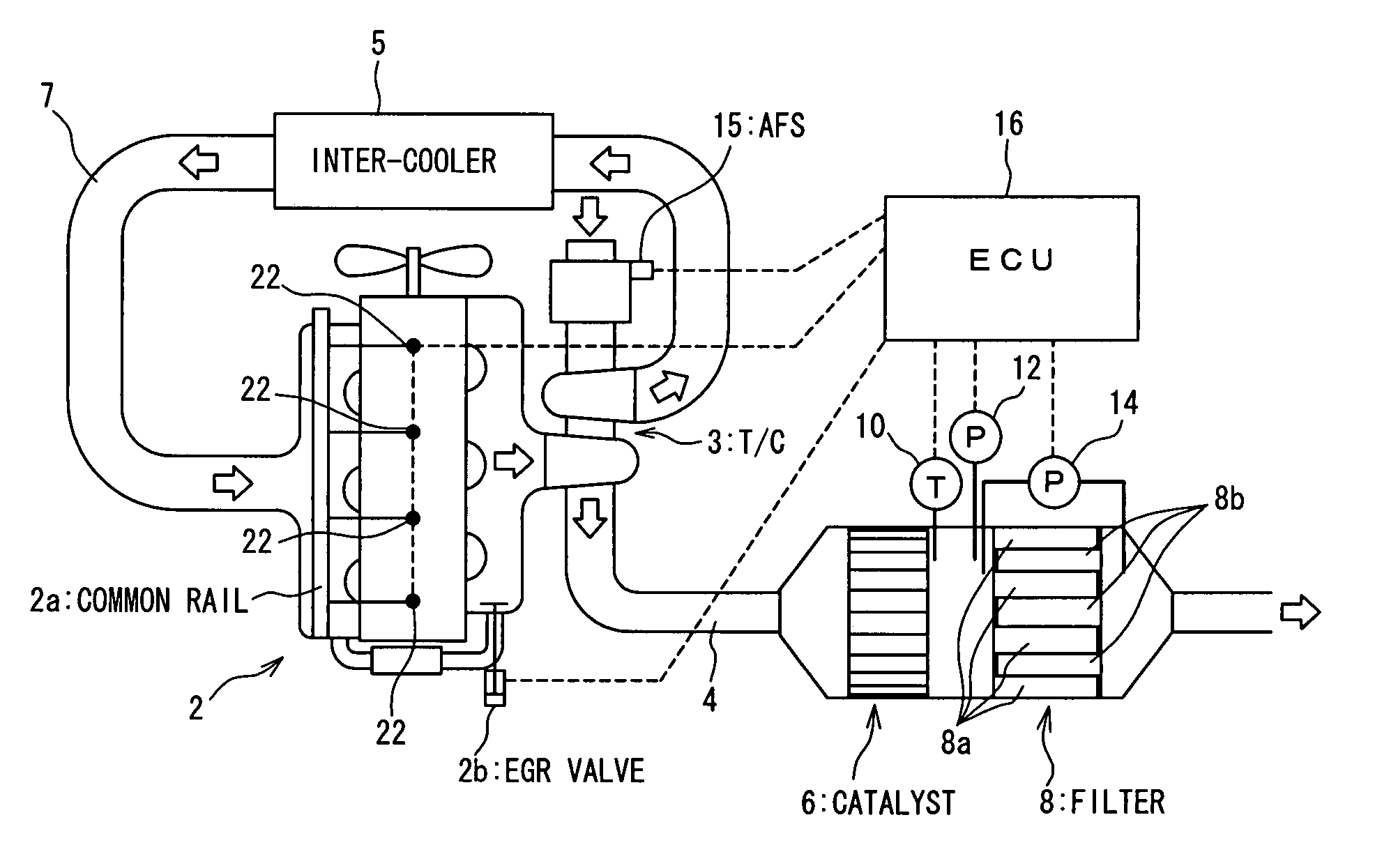
[0045]An exhaust gas purifying system according to an embodiment of the present invention will be described with reference to the accompanying drawings, in which FIG. 1 is a schematic diagram showing an entire construction of the exhaust gas purifying system. In this embodiment, an engine 2 is a diesel engine using gas oil (HC) as fuel. The engine 2 is provided with a common rail type fuel injection system wherein fuel is once stored in a high pressure storage chamber (common rail) 2a which is common to plural cylinders and is then injected.

[0046]In an exhaust passage 4 of the engine 2, an oxidation catalyst (hereinafter referred to simply as “catalyst”) 6 and a diesel particulate filter (simply “filter” hereinafter) 8 are disposed in this order from an upstream side of an exhaust gas flow. Further, a turbocharger 3 is disposed in the exhaust passage 4 and an inter-cooler 5 is disposed in an intake passage 7.

[0047]Though not shown in detail, the whole of the filter 8 is formed of a ...


PUM

PropertyMeasurementUnit
Temperatureaaaaaaaaaa
Flow rateaaaaaaaaaa
Massaaaaaaaaaa

Abstract

An exhaust gas purification system includes an oxygen mass flow rate detecting unit for detecting or calculating a mass flow rate of oxygen fed to a filter and a regeneration end determining unit for determining a regeneration end of the filter in accordance with information provided from the oxygen mass flow rate detecting-unit and upon arrival of an integrated value of the oxygen mass flow rate at a predetermined value during regeneration of the filter.

Description

BACKGROUND OF THE INVENTION[0001](1) Field of the Invention[0002]The present invention relates to an exhaust gas purifying system and a regeneration end determining method both suitable for use particularly in a diesel engine.[0003](2) Description of Related Art[0004]Heretofore, there has been known a technique wherein an oxidation catalyst and a particulate filter (hereinafter referred to simply as “filter”) are disposed in an exhaust passage of a diesel engine, allowing a particulate matter (PM) contained in exhaust gas to be deposited on the filter, and the PM thus deposited on the filter is burnt to regenerate the filter continuously.[0005]In the exhaust gas purifying system constructed as above, NO contained in exhaust gas is oxidized in the oxidation catalyst to produce NO2, then the NO2 and the PM on the filter are reacted with each other, allowing the PM to burn (be oxidized) to regenerate the filter continuously. NO2 exhibits a high function as an oxidizing agent in compari...

Claims


Application Information

Patent Timeline
IPC IPC(8): F01N3/00F01N3/02B01D46/42B01D53/96F01N3/023F01N3/025F01N3/029F01N3/035F01N3/20F01N3/24F01N9/00F01N13/02F02B29/04F02B37/00F02D41/00F02D41/02F02D41/40
CPCB01D53/96F01N13/0097F01N3/035F01N9/002F02D41/0007F02D41/029F02D41/402F01N3/0231F01N2610/03F02B29/0425F02B37/00F02B2275/14Y02T10/44Y02T10/123Y02T10/144Y02T10/47Y02T10/12Y02T10/40E04G3/00E04G5/04E04G5/06
Inventor HIRANUMA, SATOSHITAKEDA, YOSHINAKAKAWATANI, TORUDOUMEKI, REIKO
Owner MITSUBISHI FUSO TRUCK AND BUS CORPORATION
Why Eureka
Try Eureka