Internal combustion engine with localized lubrication control of combustion cylinders

Active Publication Date: 2006-09-12
DEERE & CO
View PDF8 Cites 53 Cited by
  • Summary
  • Abstract
  • Description
  • Claims
  • Application Information

AI Technical Summary

Benefits of technology

[0007]An advantage of the present invention is that the discrete indentations formed as pock marks better hold oil than conventional scratches formed in the inside surface of a combustion cylinder.
[0008]Another advantage is that the discrete indentations decrease radiation and convection heat transfer, thereby reducing volotization and pyrolysis.
[0009]Yet another advantage is that the discrete indentations provide lower oil consumption, longer particulate trap life and better performance.
[0010]A still further advantage is that the discrete indentations provide lower friction and wear resulting in longer engine life and better fuel economy.
[0011]A still further advantage is that multiple ablation manufacturing methods may be used to form the discrete indentations in the inside surface of the cylinder liner.
[0012]A further advantage is that the discrete indentations may be formed with precise uniformity and spacing.

Problems solved by technology

At these exact points where the piston changes direction, a condition of zero velocity occurs causing a reduction in hydrodynamic oil film thickness which can lead to metal-to-metal contact.
This condition is most severe at TDC because lubricating oil on the surface is exposed to combustion temperatures which may cause unfavorable changes in its viscosity.
This condition renders it more difficult to retain oil in the pores of the metal surfaces, accelerating the oil film diminishment rate subsequent to when the liner is wiped clean by the oil wipe rings situated beneath the combustion rings of the piston.
The deep scratches are not well controlled and are not conducive to the build up of a good squeeze film or hydrodynamic oil film.

Method used


Image

  • Internal combustion engine with localized lubrication control of combustion cylinders
  • Internal combustion engine with localized lubrication control of combustion cylinders
  • Internal combustion engine with localized lubrication control of combustion cylinders

Examples


Embodiment Construction

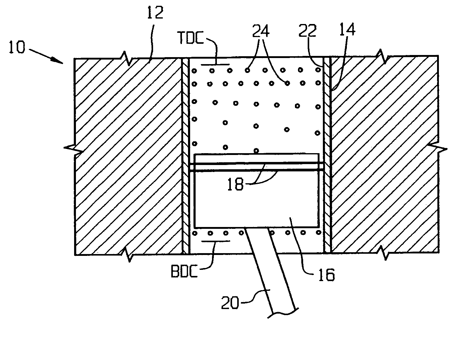
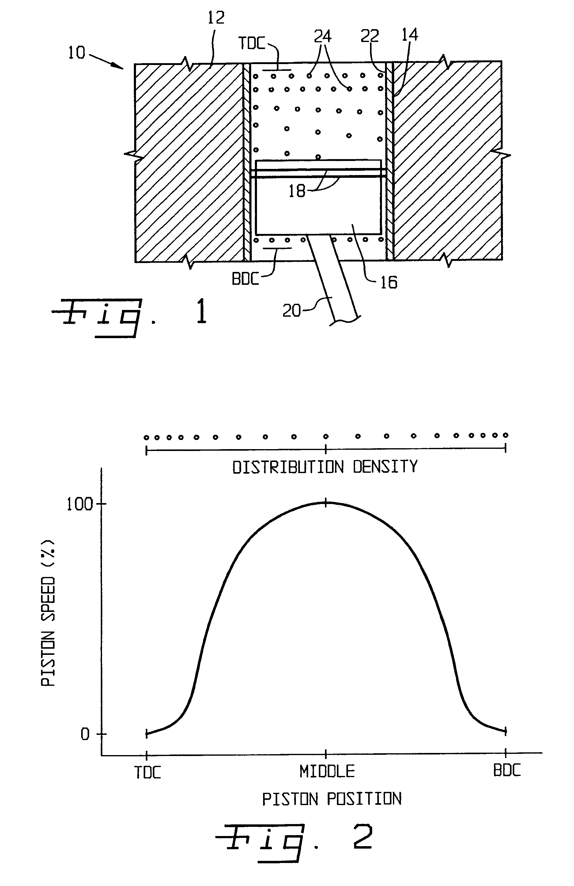
[0021]Referring now to the drawings, and more particularly to FIG. 1, there is shown a portion of an IC engine 10 of the present invention. IC engine 10 generally includes a cylinder block 12, cylinder liner 14, piston 16 carrying a pair of piston rings 18, and connecting rod 20 interconnecting piston 16 with a crankshaft (not shown). It will be appreciated that although IC engine 10 is shown with a single cylinder block 12 carrying a single cylinder liner 14, IC engine 10 typically includes multiple cylinder blocks 12, with each cylinder block carrying multiple cylinder liners defining multiple cylinders.

[0022]Piston 16 is reciprocally movable within cylinder liner 14 between a TDC position and a BDC position, indicated generally in FIG. 1. Connecting rod 20 in known manner is reciprocally connected to the crank shaft and pivotally connected to piston 16 via a pin (not shown), such that connecting rod 20 moves through an angular arc upon reciprocating movement of piston 16 within c...


PUM

PropertyMeasurementUnit
Diameteraaaaaaaaaa
Depthaaaaaaaaaa
Depthaaaaaaaaaa

Abstract

An internal combustion engine includes at least one cylinder block having at least one combustion cylinder. A number of cylinder liners are respectively associated with each combustion cylinder. Each cylinder liner defines a corresponding cylinder inside surface. Each cylinder liner includes a plurality of discrete oil retaining indentations in a predefined pattern on the cylinder inside surface. The plurality of oil retaining indentations are bounded in both peripheral and longitudinal directions of the corresponding cylinder liner.

Description

FIELD OF THE INVENTION[0001]The present invention relates to internal combustion engines, and, more particularly, to lubrication of combustion cylinders in such engines.BACKGROUND OF THE INVENTION[0002]In an internal combustion (IC) engine, when a piston reciprocally moves in sliding contact within the cylinder, friction and wear are most severe at top dead center (TDC) and bottom dead center (BDC) of the stroke positions of the piston. At these exact points where the piston changes direction, a condition of zero velocity occurs causing a reduction in hydrodynamic oil film thickness which can lead to metal-to-metal contact. This condition is most severe at TDC because lubricating oil on the surface is exposed to combustion temperatures which may cause unfavorable changes in its viscosity. This condition renders it more difficult to retain oil in the pores of the metal surfaces, accelerating the oil film diminishment rate subsequent to when the liner is wiped clean by the oil wipe ri...

Claims


Application Information

Patent Timeline
IPC IPC(8): F02F1/20
CPCF02F1/20Y10T29/49272
Inventor VUK, CARL THOMASWHITING, TODD MATHEW
Owner DEERE & CO
Why Eureka
Try Eureka