
Integrated circuit and seed layers

Inactive Publication Date: 2006-09-12
MICRON TECH INC
View PDF160 Cites 26 Cited by
  • Summary
  • Abstract
  • Description
  • Claims
  • Application Information

AI Technical Summary

Benefits of technology

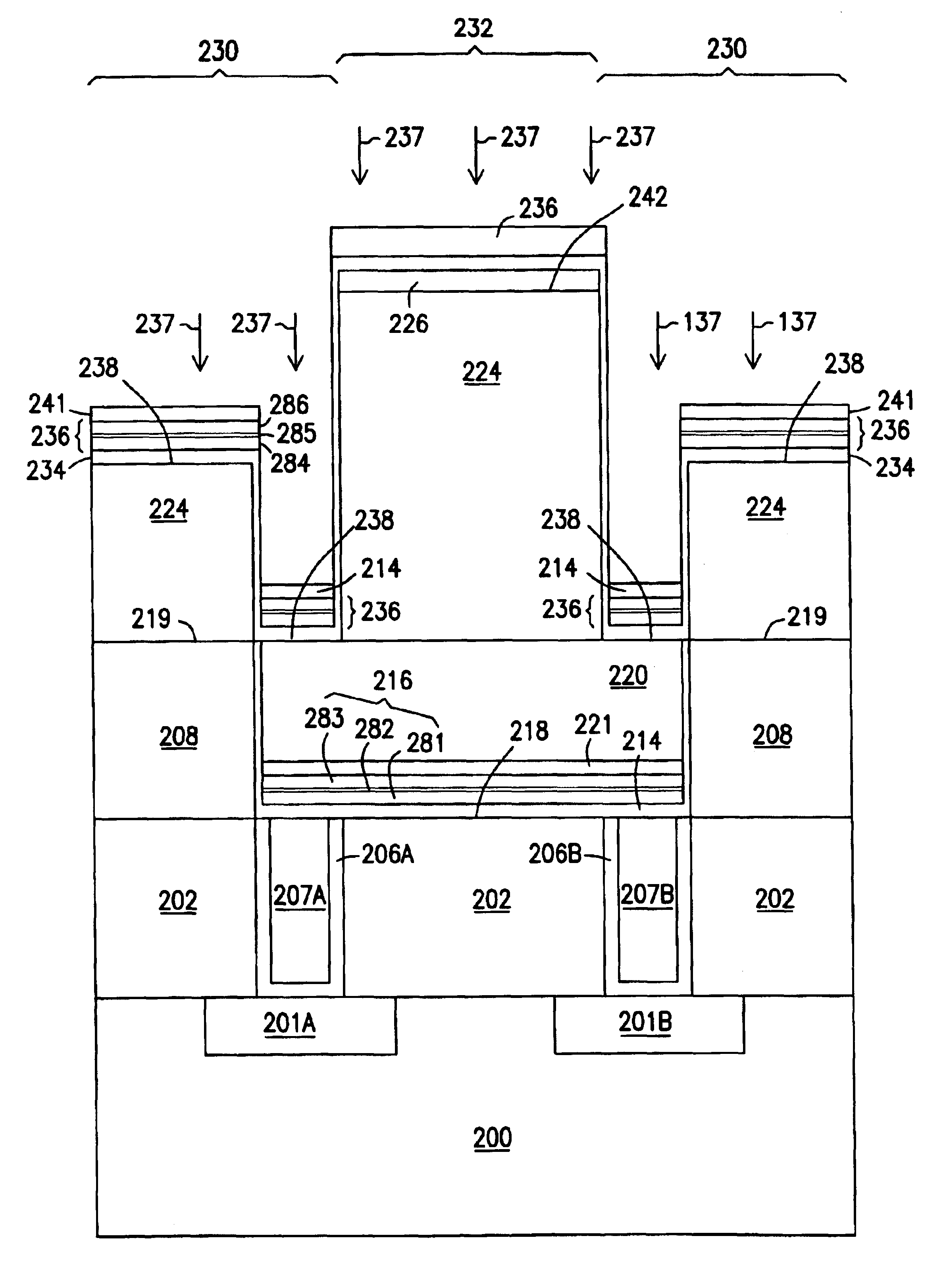
[0013]The above mentioned problems associated with integrated circuit size and performance, the via and metal line formation process, and other problems are addressed by the present invention and will be understood by reading and studying the following specification. The structures and methods of the present invention include a diffusion barrier and a seed layer in an integrated circuit both formed using a low energy ion implantation followed by a selective deposition of metal lines for the integrated circuit. According to the teachings of the present invention, the selective deposition of the metal lines avoids the need for multiple chemical mechanical planarization (CMP) steps. The low energy ion implantation of the present invention allows for the distinct placement of both the diffusion barrier and the seed layer. A residual resist can be used to remove the diffusion barrier and the seed layer from unwanted areas on a wafer surface.
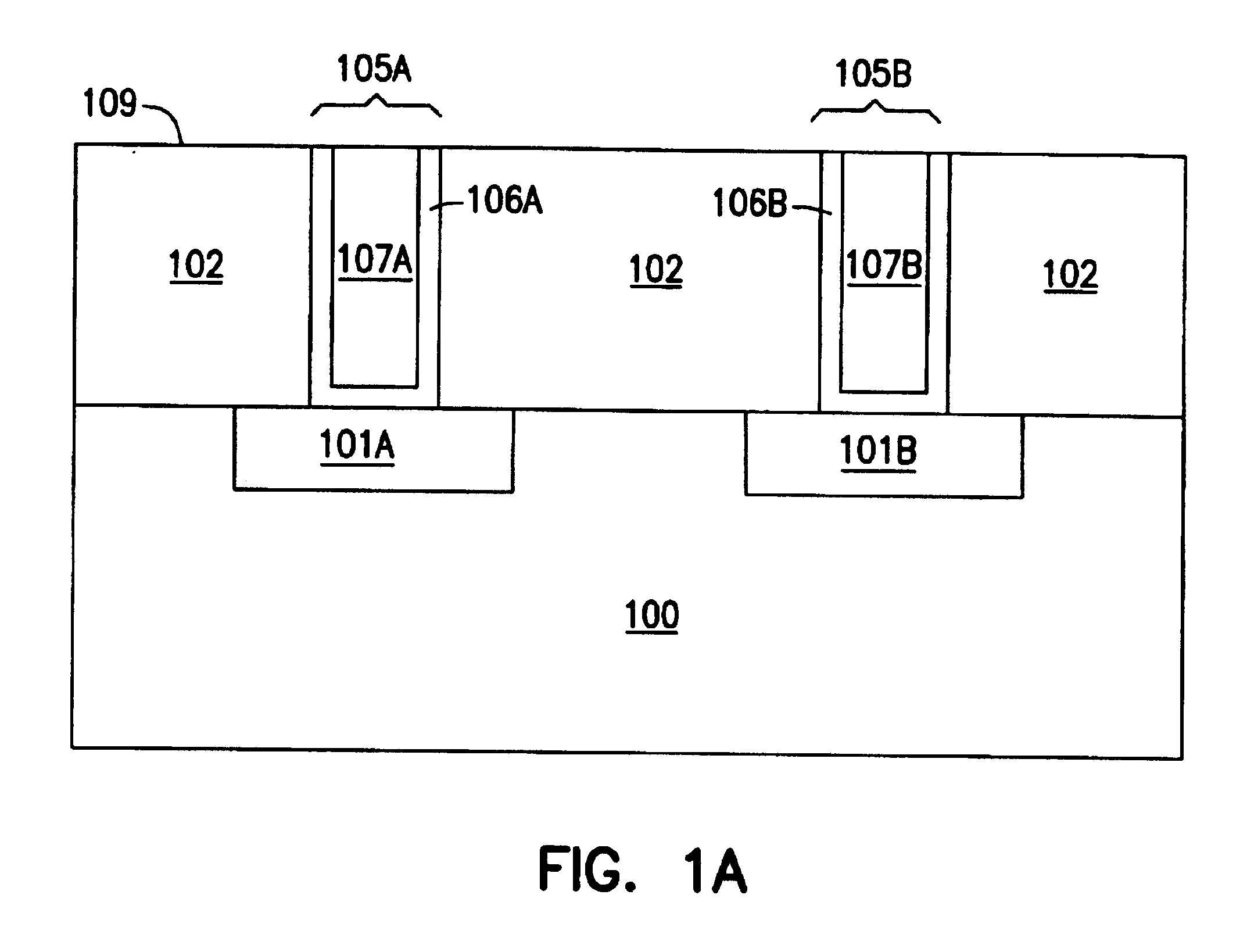
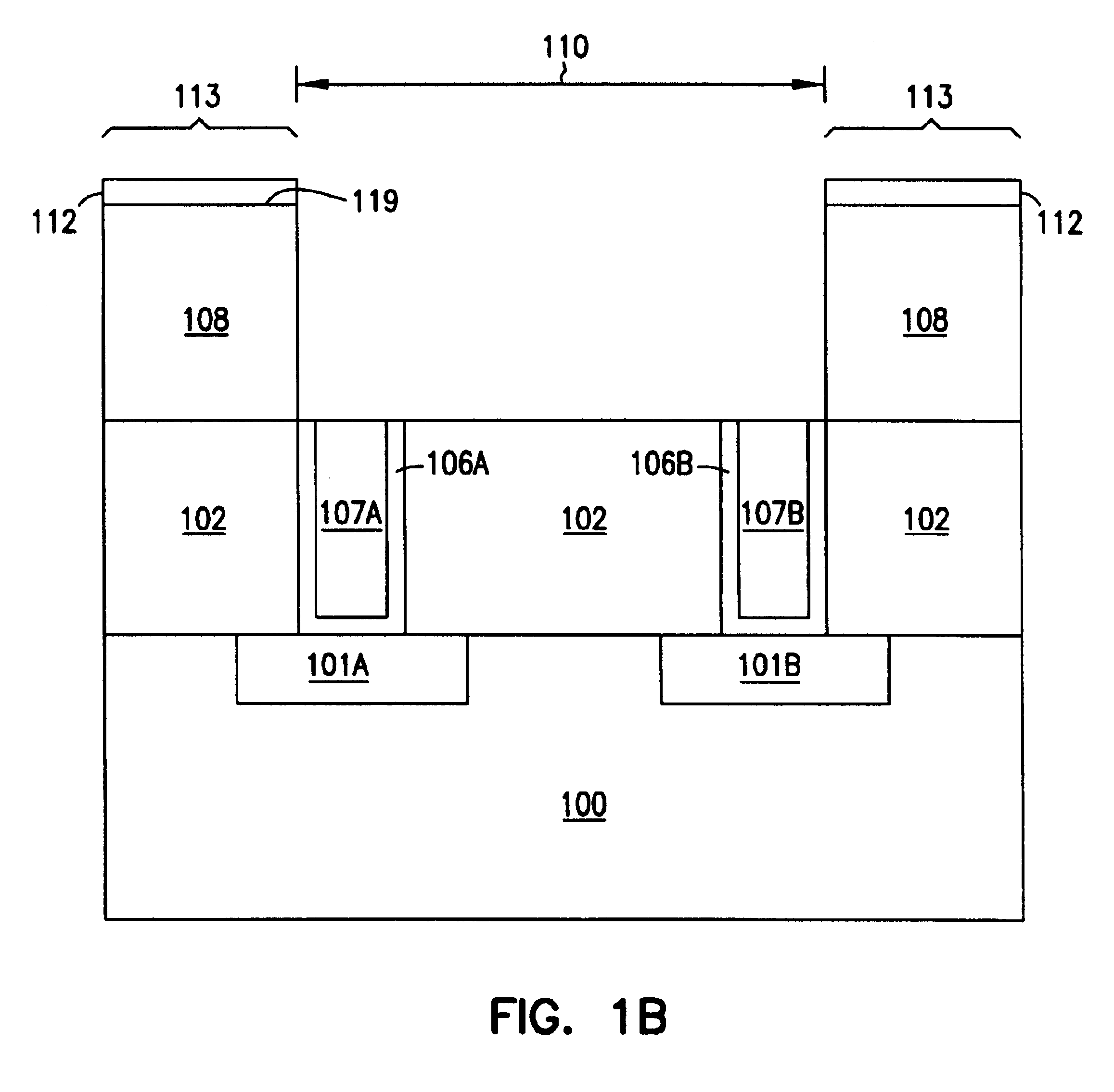
[0014]In particular one illustrative embodiment of the present invention includes a method of making a diffusion barrier and a seed layer in an integrated circuit. The method includes patterning an insulator material to define a number of trenches in the insulator layer opening to a number of first level vias in a planarized surface. A barrier / adhesion layer is deposited in the number of trenches using a low energy ion implantation, e.g. a 100 to 800 electron volt (eV) ion implantation. A seed layer is deposited on the barrier / adhesion layer in the number of trenches also using the low energy ion implantation. This novel methodology further accommodates the formation of aluminum, copper, gold, and / or silver metal interconnects.

Problems solved by technology

One of the main problems confronting the semiconductor processing industry, in the ULSI age, is that of Capacitive-Resistance loss in the wiring levels.
This has led to a large effort to reduce the resistance of and lower the capacitive loading on the wiring levels.
The capacitive resistance problem grows with each succeeding generation of technology.
Several potential problems have been encountered in the development of these proposed metallurgies.
These approaches, however, do not fully resolve the above-stated problem of the minimum line space decreases.
However as in the case of SiO2, an incompatibility problem with copper metallurgy has been found.
In addition it has been found that reactive ion etching (RIE) of all three metals, copper, silver or gold, is difficult at best.
Thus to some measure, it defeats the objectives of decreasing the capacitive loading effects.
This increases the chip cost.
However, this method may require careful process control, leading to additional expense.
However, extensive dishing in wide lines and rounding of corners of the insulator are a common occurrence.
The use of these techniques are however costly and in some cases come with density or performance penalties.
However this process has not been shown to be implementable into a product structure where a barrier and / or adhesion layer is required.

Method used


Image

  • Integrated circuit and seed layers
  • Integrated circuit and seed layers
  • Integrated circuit and seed layers

Examples


Embodiment Construction

[0022]In the following detailed description of the invention, reference is made to the accompanying drawings which form a part hereof, and in which is shown, by way of illustration, specific embodiments in which the invention may be practiced. These embodiments are described in sufficient detail to enable those skilled in the art to practice the invention. Other embodiments may be utilized and structural, logical, and electrical changes may be made without departing from the scope of the present invention.

[0023]The terms wafer and substrate used in the following description include any structure having an exposed surface with which to form the integrated circuit (IC) structure of the invention. The term substrate is understood to include semiconductor wafers. The term substrate is also used to refer to semiconductor structures during processing, and may include other layers that have been fabricated thereupon. Substrate include doped and unhoped semiconductors, epitaxial semiconduct...


PUM


Abstract

Structures are provided which improve performance in integrated circuits. The structures include a diffusion barrier and a seed layer in an integrated circuit both formed using a low energy ion implantation followed by a selective deposition of metal lines for the integrated circuit. The low energy ion implantation allows for the distinct placement of both the diffusion barrier and the seed layer. Structures are formed with a barrier / adhesion layer deposited in the number of trenches using a low energy ion implantation, e.g. a 100 to 800 electron volt (eV) ion implantation. A seed layer is deposited on the barrier / adhesion layer in the number of trenches also using the low energy ion implantation. Such structures include aluminum, copper, gold, and silver metal interconnects.

Description

RELATED APPLICATIONS[0001]This application is a Divisional of U.S. application Ser. No. 09 / 484,002, filed Jan. 18, 2000 now U.S. Pat. No. 6,376,370, which is incorporated herewith.[0002]This application is related to the following co-pending, commonly assigned applications: U.S. application Ser. No. 09 / 128,859 filed Aug. 4, 1998, now U.S. Pat. No. 6,284,656, U.S. application Ser. No. 09 / 488,098, filed Jan. 18, 2000, now U.S. Pat. No. 6,429,120, and U.S. application Ser. No. 09 / 484,303, filed Jan. 18, 2000, which are hereby incorporated by reference.FIELD OF THE INVENTION[0003]The present invention relates generally to integrated circuits. More particularly, it pertains to structures and methods for providing seed layers for integrated circuit metallurgy.BACKGROUND OF THE INVENTION[0004]One of the main problems confronting the semiconductor processing industry, in the ULSI age, is that of Capacitive-Resistance loss in the wiring levels. This has led to a large effort to reduce the re...

Claims


Application Information

Patent Timeline
IPC IPC(8): H01L23/58H01L21/768
CPCH01L21/76843H01L21/76846H01L21/76849H01L21/76867H01L21/76874H01L21/76885H01L21/76859H01L2221/1089H01L21/768
Inventor FARRAR, PAUL A.
Owner MICRON TECH INC
Learn More