Method of dynamically charging a battery using load profile parameters

a battery and load profile technology, applied in secondary cells, electrochemical generators, instruments, etc., can solve the problems of not being able to provide the most useful optimization method, not being able to provide “real-time” adaptation of the charging regimen, and not being able to account for more power-based applications

Inactive Publication Date: 2006-09-12
ENERDEL
View PDF12 Cites 33 Cited by
  • Summary
  • Abstract
  • Description
  • Claims
  • Application Information

AI Technical Summary

Benefits of technology

[0006]An object of the present invention is to solve one or more of the problems as set forth above. One advantage of the present invention is that the energy system, which may be formed of a fuel cell or any bi-directional energy storage devices such as lithium chemistry technologies, is able to continuously self-learn its operating trends in “real time,” thereby allowing it to tune itself to optimize performance either while the energy system is “live” in operation, or while the system is “off-line.” The present invention allows the system to adapt itself to whatever type of load profile, whether it be of a more constant, energy-based nature, or of a more dynamic, power based nature that is presented to it by an associated application. This allows the system to then adapt a charging strategy that is appropriate for that given load profile. The continuous adaptation to the performance of the energy system as presented in this invention allows for performance of the energy system to be optimized and extracted beyond what is normally expected.
[0007]Another advantage is that the measurements made in accordance with the present invention are done so in real-time as the system is live in operation without requiring any additional monitoring circuitry, or any user interaction.
[0008]These and other features, objects, and advantages are realized by the present invention, which includes a method of operating an energy system. The method includes measuring the electrical characteristics of power (i.e., current and voltage) drawn by an application coupled to the energy system, and storing these measurements in a memory to create a running series of time-based measurements. The method further includes processing the measured electrical characteristics stored in the memory to produce an energy spectra and a power spectra of the load profile presented by the application to the energy system, and then adjusting the charging strategy of the energy system in accordance with the energy spectra and power spectra.
[0009]An energy system according to the invention is also presented.

Problems solved by technology

With respect to energy systems comprised of lithium chemistry technologies, fixed energy-based balancing methods are utilized in an effort to maximize performance for energy-based applications and load profiles, however, no provisions are made to account for more power-based applications.
These existing methods, while adequate, do not allow for the most useful method of optimization.
Existing methods, as set forth above, neither provide for “real time” adaptation of the charging regimen to the energy system while it is “live” in operation, nor take into account the varied applications that may be presented to an energy system.
For example, while it would generally be desirable to charge the battery to its highest possible state of charge for more constant, energy-based applications presented to the energy system (which in turn would provide the greatest range or longest duration use for the application running off the battery), such an approach is generally not considered optimal for more dynamic, power-based applications.

Method used


Image

  • Method of dynamically charging a battery using load profile parameters
  • Method of dynamically charging a battery using load profile parameters
  • Method of dynamically charging a battery using load profile parameters

Examples


Embodiment Construction

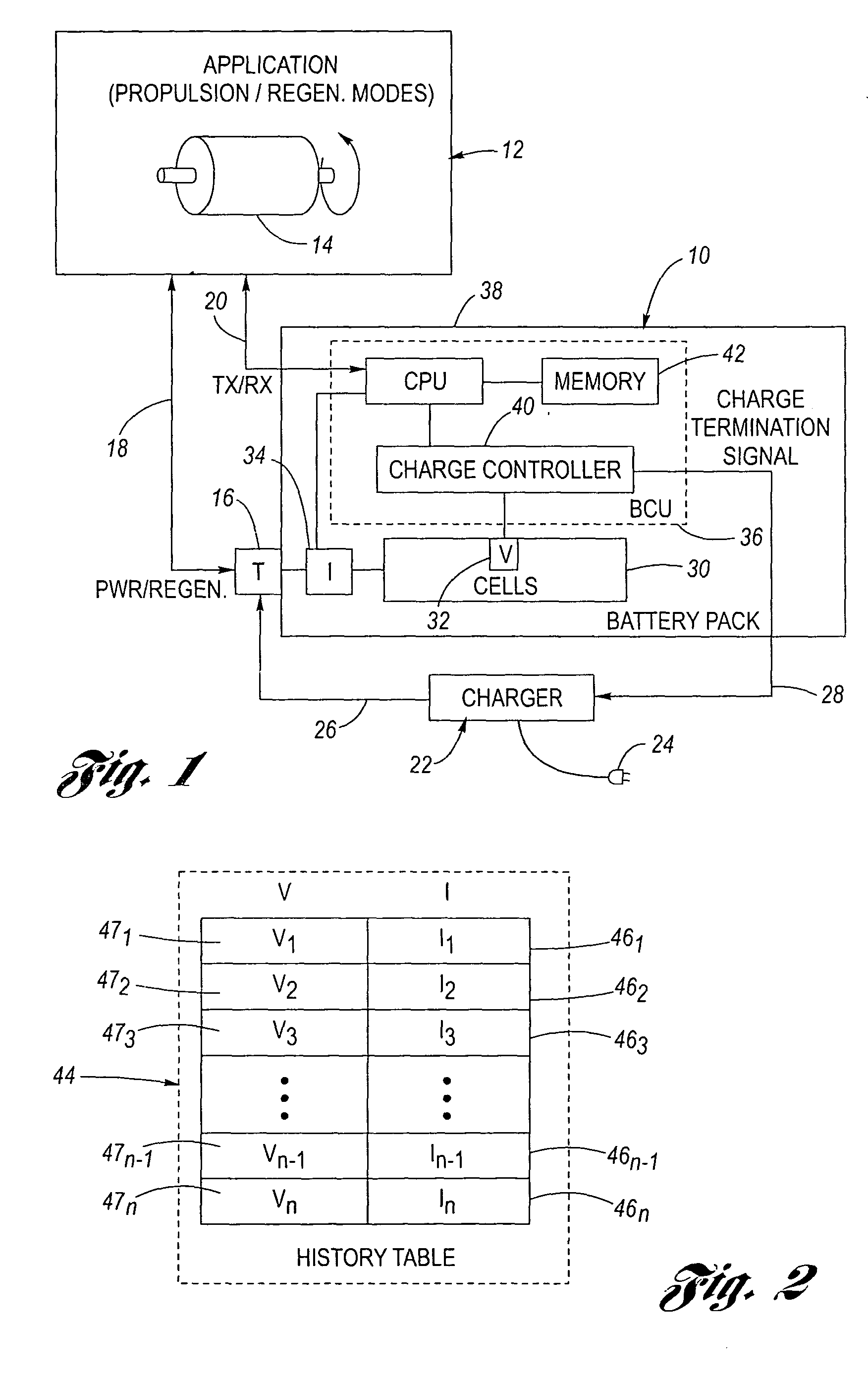
[0015]Referring now to the drawings wherein like reference numerals are used to identify identical components in the various views, FIG. 1 is a simplified, schematic and block diagram view of an inventive energy system 10 according to the invention suitable for use in connection with any one or more of a plurality of exemplary applications 12. Application 12, in the illustrated embodiment, may be of the type employing a dynamoelectric machine 14, which may alternatively be configured for operation (i) in a first mode wherein the machine 14 is used for propulsion torque, or (ii) in a second mode different from the first mode wherein the machine 14 is configured for the production of regenerative energy (i.e., it is configured as a generator). For example, such applications may include, but are not limited to, self-propelled vehicle applications, although other application stationary in nature (i.e., rotating systems having loads with inertia) are also included within the spirit and s...


PUM

PropertyMeasurementUnit
electrical characteristicsaaaaaaaaaa
voltageaaaaaaaaaa
energy spectraaaaaaaaaaa

Abstract

An energy system is formed of a plurality of battery cells, and has an application associated therewith that draws power from the energy system, thereby creating a load profile that is presented to the energy system. As the application is being used, voltage and current measurements are taken at a predetermined rate, and stored in a history table to create a series of time-based measurements. The measurements stored in the history table are then processed to produce an energy spectra and a power spectra corresponding to the load profile presented to the energy system by the application. A charging strategy in accordance with this energy spectra and power spectra is then defined and used to charge the energy system appropriately.

Description

TECHNICAL FIELD[0001]The invention relates generally to energy-based systems, and in particular to a method of operating these systems.BACKGROUND OF THE INVENTION[0002]It is known in many applications, including self-propelled vehicle applications as seen by reference to U.S. Pat. No. 6,394,208 entitled “STARTER / ALTERNATOR CONTROL STRATEGY TO ENHANCE DRIVEABILITY OF A LOW STORAGE REQUIREMENT HYBRID ELECTRIC VEHICLE” issued to Hampo et al., to employ a dynamoelectric machine in a first mode as a motor in order to provide propulsion torque. In such applications, it is also known to reconfigure the dynamoelectric machine in a second mode as a generator, in order to capture and convert some of the potential or kinetic energy associated with the application into output electrical power, a process known as regeneration (“regenerative energy”). Moreover, in such applications, it is also known to provide an energy system, such as a battery, to power the dynamoelectric machine when operated ...

Claims


Application Information

Patent Timeline
Patent Type & Authority Patents(United States)
IPC IPC(8): H01M10/44H01M10/46H02J7/14
CPCH02J7/1438H02J7/1461Y02E60/76Y04S40/22H02J2003/007H02J2203/20Y02E60/00Y04S40/20H02J7/0048
Inventor MOORE, STEPHEN W.
Owner ENERDEL
Why Eureka
Try Eureka