Dynamically reconfigurable vision system

a vision system and dynamic reconfiguration technology, applied in the field of vision systems, can solve the problems of high cost, high power consumption, complex equipment, etc., and achieve the effect of efficient use of bandwidth and data processing resources

Inactive Publication Date: 2006-09-12
COMPTEK AMHERST SYST INC
View PDF36 Cites 163 Cited by
  • Summary
  • Abstract
  • Description
  • Claims
  • Application Information

AI Technical Summary

Benefits of technology

[0011]It is the principal object of the present invention to provide an improved vision system having a dynamically reconfigurable photodetector array that efficiently uses bandwidth and data processing resources.

Problems solved by technology

Hence, traditional imaging systems that employ uniform and constant spatial resolution throughout the entire field of view acquire much irrelevant information and thus burden valuable data processing and communication resources in the system.
As a result, such systems are slow and do not operate at their full potential due to a flood of unimportant video information.
Building vision systems with multiple cameras, several processors, high-bandwidth communication links, and specialized hardware will increase performance, but results in equipment that is complex, expensive, large, heavy, high power consuming, and prone to failures.
These constraints make constant resolution vision systems difficult or impossible to use where space, speed of response, and reliability are critical considerations, for instance, in defense applications.
Because high-resolution imaging is limited to the fovea, which is fixed in the center of the retina, the tracking of targets involves movement of the eyes and the head.
Several vision systems or imaging photodetector arrays have been developed which do not enable DRV.
These vision systems and sensors do not provide a reduction in the amount of irrelevant information sensed through the use of a computer-controlled system for imaging a scene through multiple independently controllable, time-correlated, overlapping sensor windows.
This circuitry requires the host computer to send control signals to the sensor for the extraction of the signal from each superpixel, and like the other prior art system, do not provide imaging a scene through a multiple independently controllable, time-correlated, overlapping sensor windows.
This is time consuming and reduces bandwidth by increasing the amount of interaction between the computer and the camera.
This operation requires extra time and system memory, thus slowing down the image processing.
Moreover, because the pixels in this patent are exposed at different times, any motion in the field of view (due to camera and / or target motion) will introduce artifacts, such as target warping, artifacts that reduce the accuracy of the target classification.
Such arrays are not reconfigurable, do not operate in a closed loop fashion with the vision processor, and require a pointing mechanism for gazing.
Mechanical pointing suffers from instabilities and is slow.
Further, because the topology of the array in a fixed geometry system cannot be changed on demand, some relevant regions of the scene may not be resolved adequately, as a result sacrificing system reliability and usefulness, while the irrelevant regions may be resolved too finely, hence reducing the efficiency of system resource utilization.
As a result, the communications bandwidth and the video processing resources are not used any more efficiently than in a conventional uniform resolution camera.

Method used


Image

  • Dynamically reconfigurable vision system
  • Dynamically reconfigurable vision system
  • Dynamically reconfigurable vision system

Examples


Embodiment Construction

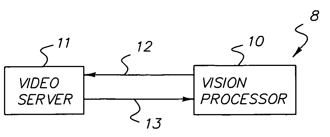
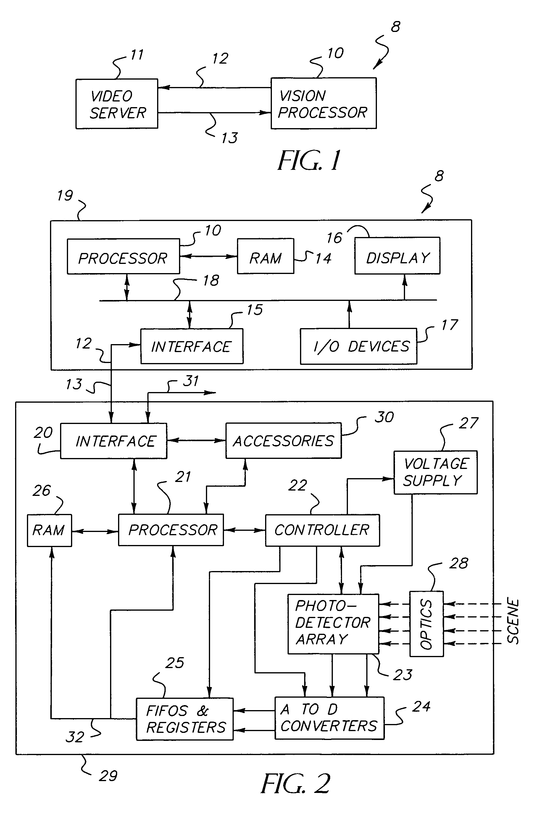
[0029]Referring to FIG. 1, a block diagram of the essential components of the DRV system 8 of the present invention is shown having two major modules: a reconfigurable video server 11 (typically embodied as a reconfigurable photodetector array within a video camera) and a vision processor 10. These two components are connected in a closed-loop, client-server relationship. A server represents an object that is waiting to be contacted by a client object so that the server can do something for the client. In DRV system 8, the server 11 is the reconfigurable photodetector array 23 in the video camera 29 and the client is the vision processor 10. The client vision processor in the computer 19 is programmed to generate commands, known as window request commands, that specify the spatial and temporal requirements (characteristics or configuration) of the video to be sensed on the reconfigurable photodetector array 23 in the video server 11. These window request commands are transmitted to ...


PUM


Abstract

A closed-loop vision system is disclosed that utilizes a concept known as Dynamically Reconfigurable Vision (DRV), which is adaptive image sensing driven by a computer or human operator's response to changing scenery. The system reduces the amount of irrelevant video information sensed and thus achieves more effective bandwidth and computational resource utilization, as compared to traditional vision systems. One or more reconfigurable photodetector arrays sensitive to either visible, infrared or ultraviolet radiation are present in the DRV system. These photodetector arrays feature on-chip means for spatial and temporal data reduction implemented through multiple independently controllable, time-correlated, frequently overlapping windows on the photodetector array that may be programmed according to their size, location, resolution, integration time, and frame rate. All photodetector array windows are dynamically reconfigurable in real time on a frame-by-frame basis. Furthermore, a DRV system is constructed in a client-server architecture in which a vision processor client passes window request command messages to the reconfigurable photodetector array server, which in turn delivers the requested video back to the client processor. The ability to simultaneously reconfigure, integrate, process, and readout multiple photodetector array video windows is an important characteristic of the DRV system.

Description

[0001]This Application claims the benefit of priority to U.S. Provisional Application No. 60 / 127,698, filed Apr. 5, 1999, which in herein incorporated by reference.FIELD OF INVENTION[0002]The present invention is related to a vision system (and method), and related particularly to a vision system having reconfigurable CMOS video photodetector arrays providing multiple, time-correlated, overlapping, programmable photodetector array windows. The invention is suitable for single or multiple target viewing, detection, tracking, and identification, especially where such applications are constrained by requirements of limited bandwidth, processing capability, space, weight, or power.BACKGROUND OF INVENTION[0003]Vision systems for detecting, identifying, and tracking targets must acquire and process large volumes of video data in real time. Most applications requiring these tasks, however, are characterized by imagery where targets and other objects of interest occupy only a small fraction...

Claims


Application Information

Patent Timeline
Patent Type & Authority Patents(United States)
IPC IPC(8): H04N5/335H04N5/232H04N5/262H04N5/374
CPCH04N5/23206H04N5/232H04N23/951
Inventor BANDERA, CESARSTACK, DAVID J.KRAMER, CHRISTOPHERMCLOUGHLIN, TERENCE H.
Owner COMPTEK AMHERST SYST INC
Why Eureka
Try Eureka