Method of adjusting axial direction of monitoring apparatus

a technology of axial direction and monitoring apparatus, which is applied in the direction of distance measurement, instruments, and using reradiation, etc., can solve the problems of large error between the measured position of the monitoring apparatus and the actual position, the relative positional relationship between the radar and the camera may become inappropriate, and the error accumulation between the sensors, etc., to achieve the effect of mass production of vehicles

Inactive Publication Date: 2006-09-12
ORMON CORP
View PDF2 Cites 65 Cited by
  • Summary
  • Abstract
  • Description
  • Claims
  • Application Information

AI Technical Summary

Benefits of technology

[0038]Another way of adjusting the axial displacement is to use the processing device as described above to obtain axial displacement data related to axial displacement of the first detection area or the second detection area based on the results of measurement by the radar or the image of the target taken by the camera, to cause the displacement data to be displayed on a display, and to cause a user to change the first detection area or the second detection area while observing the display until the axial displacement of the first detection area or the second detection area comes to be within a specified range. Although this method involves the work of the user, since the user can make the adjustment while observing the data on the display, a highly developed skill is not required for the work and a correct adjustment can be effected relatively easily and inexpensively.
[0039]In methods according to both the first and second embodiments of the invention, it is desirable to make use of a control device for the radar and / or the camera of the monitoring apparatus such that axial detection operations can be carried out automatically and also a processing device for automatically adjusting the position and orientation of the attachment of the monitoring apparatus or changing the parameter for the detection area such that the entire adjustment operations can be automated although some simple operations such as specifying a range and specifying crossing points may be done by a user. In such a case, the user has only to give a command after carrying out a simple operation such that complicated adjustments in the perpendicular direction need no longer be done by a person. Thus, the present invention contributes significantly to improving, for example, the efficiency in mass production of vehicles.

Problems solved by technology

For this reason, even after the axial direction is adjusted by a prior art method, a significantly large error could take place between the measured position by the monitoring apparatus and the actual position near the edge of a detection area because of such displacement in the rolling direction.
Moreover, since different targets are used individually for the axial adjustments of the radar and the camera by a prior art method, there was the following problem in the case of a fusion type which uses both a radar and a camera at the same time.
If the prior art method of axial adjustment is applied to the fusion type, there is the possibility that the relative positional relationship between the radar and the camera may become inappropriate (with the axes of the detection areas of the two sensors not being parallel or with the two sensors oriented differently with respect to the rolling direction) due to errors in the positions at which the targets or marks are set.
It is because there may be an error in the positioning of each target with respect to the vehicle that these errors accumulate between the sensors.
It is also because the displacement of each of the sensors from the direction of rolling is not adjusted that the orientations of their detection areas do not match in the direction of the rolling.
If the relative positional relationship between the two sensors remains thus incorrect, correlation between observed data by the two sensors used in the fusion method cannot be taken properly and this means that there is no advantage in using the fusion method.

Method used


Image

  • Method of adjusting axial direction of monitoring apparatus
  • Method of adjusting axial direction of monitoring apparatus
  • Method of adjusting axial direction of monitoring apparatus

Examples


Embodiment Construction

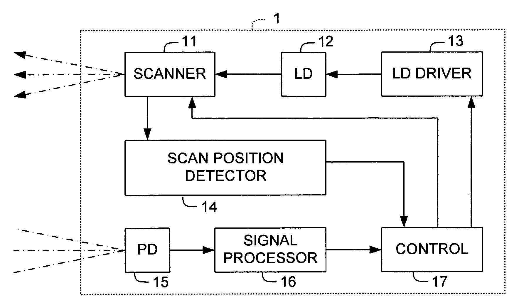
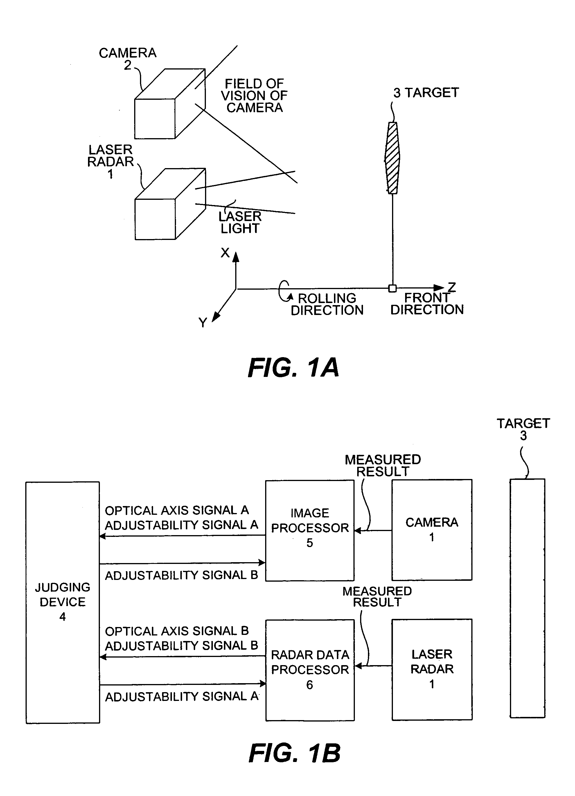
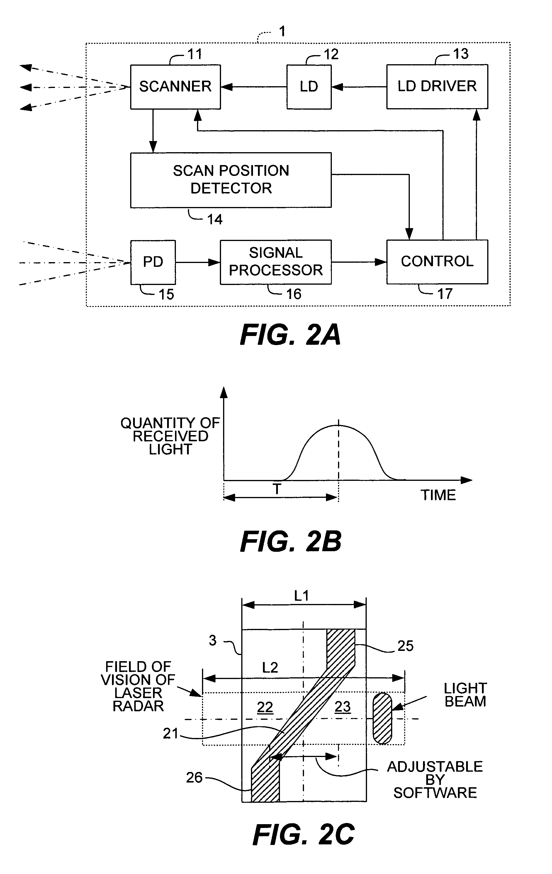
[0053]FIGS. 1A, 1B, 2A, 2B and 2C show the structure of a system including a monitoring apparatus provided with a laser radar and a camera to be mounted to a vehicle on which a method embodying this invention may be carried out, FIG. 1A showing its main structure, FIG. 1B being a block diagram of the control system of the monitoring apparatus, FIG. 2A being a block diagram of the laser radar, FIG. 2B being a drawing for explaining the principle of measurement by the laser radar, and FIG. 2C being a front view of a target used for the adjustment.

[0054]FIG. 1A shows a laser radar (hereinafter referred to simply as the radar) 1 and a camera 2 both mounted to a vehicle. The radar 1 is of a type for scanning both in the horizontal and vertical directions (respectively the standard and perpendicular directions). Numeral 3 indicates a target used for the adjustment. X, Y and Z in FIG. 1A indicates a coordinate system fixed to the vehicle, the X-axis being in the vertical direction, the Y-a...


PUM


Abstract

A method for a monitoring apparatus using a radar and a camera to detect an object. The radar and the camera each have its own detection area and the method is for detecting and correcting the displacement of each detection area by using a single target having dark and bright parts formed in a specified pattern on its surface and placing it in front of the apparatus where the two detection areas overlap. The direction and orientation of the detection area of the radar are measured and corrected and then the detection area of the camera is corrected. The pattern includes an elongated dark part flanked by a pair of bright parts such that quantity of reflected light obtained by scanning the detection surface has a distribution with waveform having two peaks and a valley in between and corrections on the detection areas are made by analyzing their positions.

Description

BACKGROUND OF THE INVENTION[0001]This invention relates to a monitoring apparatus such as a radar adapted to be mounted to a vehicle for using electromagnetic waves such as laser light to obtain position data of an object of detection such as a front-running vehicle and more particularly to a method of adjusting the orientation of its detection area, or its axial direction.[0002]Apparatus of this type adapted to be mounted to a vehicle for monitoring front-running vehicles or for cruising (or car-following) control have long been in development and it has been known to use electromagnetic waves including laser light for this purpose, or an apparatus adapted to transmit electromagnetic waves such as laser light to a target object of detection within a specified detection area and to obtain data such as the distance to the object from the delay time of a reflected signal therefrom.[0003]In the case of a laser radar, for example, a timing for light-emission is generated by a control ci...

Claims


Application Information

Patent Timeline
Patent Type & Authority Patents(United States)
IPC IPC(8): G01C3/08G01B11/26G01C1/00G01S7/497G01S13/00G01S17/931
CPCG01S7/4972G01S17/936G01S17/931
Inventor MATSUURA, YOSHIOHORIBE, KOJI
Owner ORMON CORP
Why Eureka
Try Eureka