Systems and methods for imaging large field-of-view objects

a large field of view object and imaging system technology, applied in the field of imaging systems and methods, can solve the problems of reducing the accuracy of image reconstruction, so as to avoid the effect of corrupted and resulting artifacts, minimizing and avoiding the effect of reducing the amount of missing data

Inactive Publication Date: 2006-09-19
MEDTRONIC NAVIGATION
View PDF78 Cites 501 Cited by
  • Summary
  • Abstract
  • Description
  • Claims
  • Application Information

AI Technical Summary

Benefits of technology

[0007]The present invention relates to radiation-based imaging, including 3D computerized tomography (CT) and 2D planar x-ray imaging. In particular this invention relates to methods and systems for minimizing the amou

Problems solved by technology

One drawback to this method is that acquiring the 3D data set one slice at a time is an inherently slow process.
There are other problems with this conventional tomographic technique, such as motion artifacts arising from the fact that the slices cannot be imaged simultaneously, and excessive exposure to x-ray radiation due to overlap of the x-ray projection areas.
A significant limitation of existing cone-beam reconstruction techniques occurs, however, when the object being imaged is larger than the field-of-view of the detector, which is a quite common situation in both industrial and medical imagin

Method used


Image

  • Systems and methods for imaging large field-of-view objects
  • Systems and methods for imaging large field-of-view objects
  • Systems and methods for imaging large field-of-view objects

Examples


Embodiment Construction

[0032]A description of preferred embodiments of the invention follows.

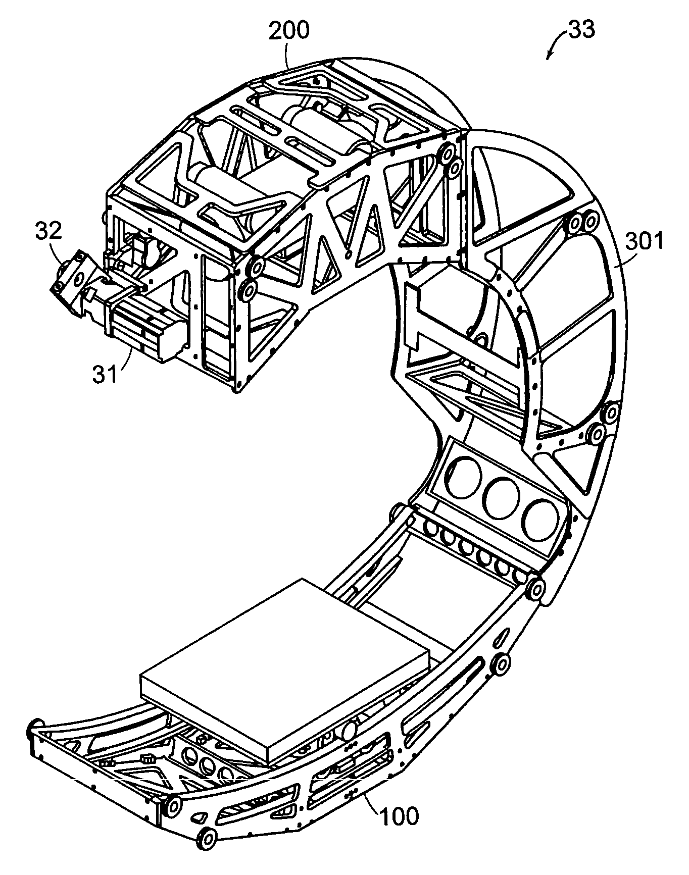
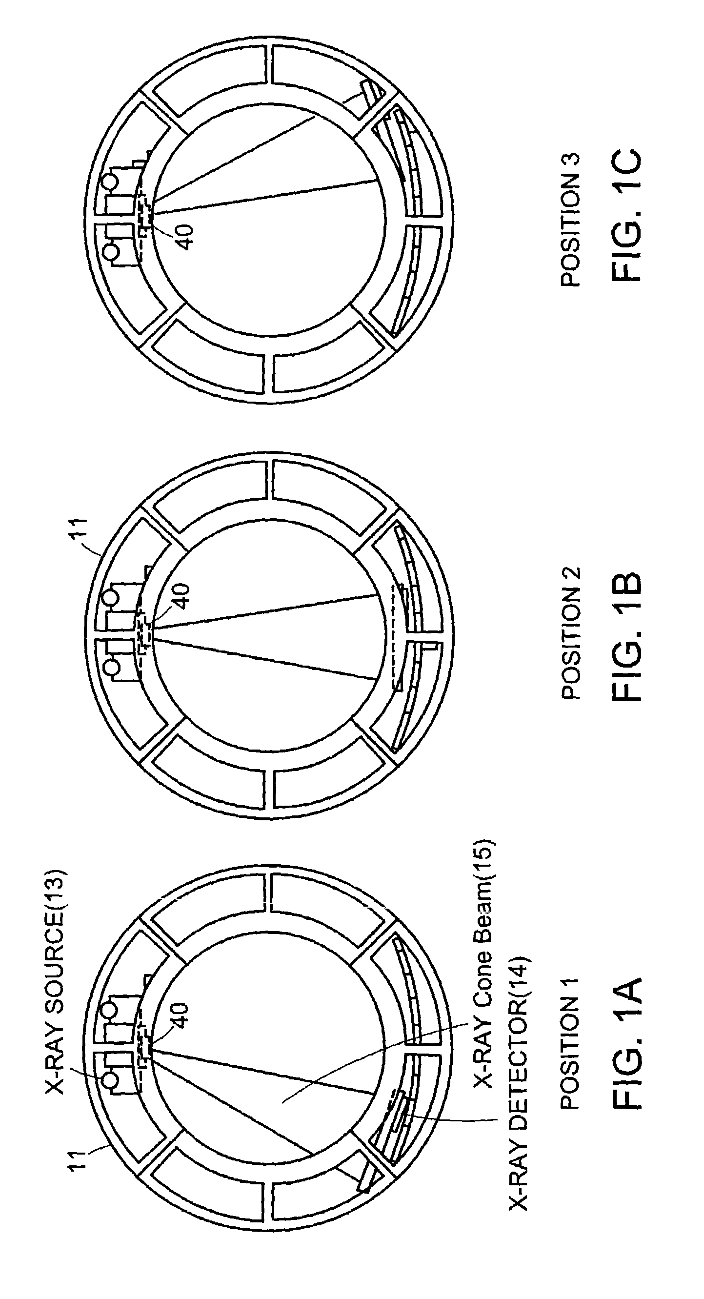
[0033]FIGS. 1A–C schematically illustrate an x-ray scanning system with a translating detector array according to one embodiment of the invention. The scanning system shown in FIGS. 1A–C includes gantry 11, which in this embodiment comprises a generally circular, or “O-shaped,” housing having a central opening into which an object being imaged is placed. The gantry 11 contains an x-ray source 13 (such as a rotating anode pulsed x-ray source) that projects a beam of x-ray radiation 15 into the central opening of the gantry, through the object being imaged, and onto a detector array 14 (such as a flat panel digital detector array) located on the opposite side of the gantry. The x-rays received at the detector 14 can then be used to produce a 2D planar or 3D tomographic object reconstruction images using well-known techniques.

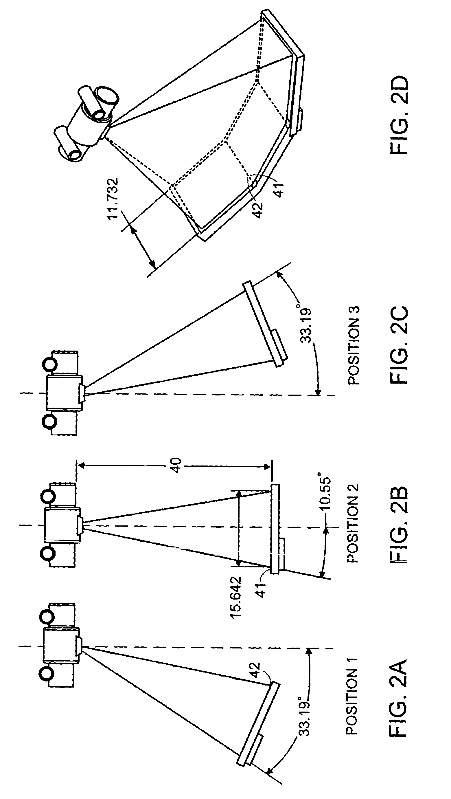
[0034]The detector 14 is translated to multiple positions along a line or arc in a direction...


PUM


Abstract

An imaging apparatus and related method comprising a source that projects a beam of radiation in a first trajectory; a detector located a distance from the source and positioned to receive the beam of radiation in the first trajectory; an imaging area between the source and the detector, the radiation beam from the source passing through a portion of the imaging area before it is received at the detector; a detector positioner that translates the detector to a second position in a first direction that is substantially normal to the first trajectory; and a beam positioner that alters the trajectory of the radiation beam to direct the beam onto the detector located at the second position. The radiation source can be an x-ray cone-beam source, and the detector can be a two-dimensional flat-panel detector array. The invention can be used to image objects larger than the field-of-view of the detector by translating the detector array to multiple positions, and obtaining images at each position, resulting in an effectively large field-of-view using only a single detector array having a relatively small size. A beam positioner permits the trajectory of the beam to follow the path of the translating detector, which permits safer and more efficient dose utilization, as generally only the region of the target object that is within the field-of-view of the detector at any given time will be exposed to potentially harmful radiation.

Description

RELATED APPLICATION[0001]This application claims the benefit of U.S. Provisional Application No. 60 / 366,062, filed Mar. 19, 2002, the entire teachings of which are incorporated herein by reference.BACKGROUND OF THE INVENTION[0002]In conventional computerized tomography for both medical and industrial applications, an x-ray fan beam and a linear array detector are employed to achieve two-dimensional axial imaging. The quality of these two-dimensional (2D) images is high, although only a single slice of an object can be imaged at a time. To acquire a three-dimensional (3D) data set, a series of 2D images are sequentially obtained in what is known as the “stack of slices” technique. One drawback to this method is that acquiring the 3D data set one slice at a time is an inherently slow process. There are other problems with this conventional tomographic technique, such as motion artifacts arising from the fact that the slices cannot be imaged simultaneously, and excessive exposure to x-...

Claims


Application Information

Patent Timeline
IPC IPC(8): H05G1/04A61B6/00A61B6/03G21K5/10
CPCA61B6/032A61B6/4021A61B6/4233G01N23/046A61B6/4452A61B6/4405G01N2223/419G01N23/043A61B6/06A61B6/4085
Inventor GREGERSON, EUGENE A.GRANT, RICHARD K.JOHNSON, NORBERT
Owner MEDTRONIC NAVIGATION
Why Eureka
Try Eureka