

Method and apparatus for optical transmission
a technology of optical transmission and optical transmission, applied in the field of optical transmission equipment and methods, can solve the problems of increasing the number of wavelengths by doubling the bandwidth of each repeater, affecting the operation of the entire system, so as to reduce the scale of circuitry
- Summary
- Abstract
- Description
- Claims
- Application Information
AI Technical Summary
Benefits of technology
Problems solved by technology
Method used
Image

Examples
embodiment 1
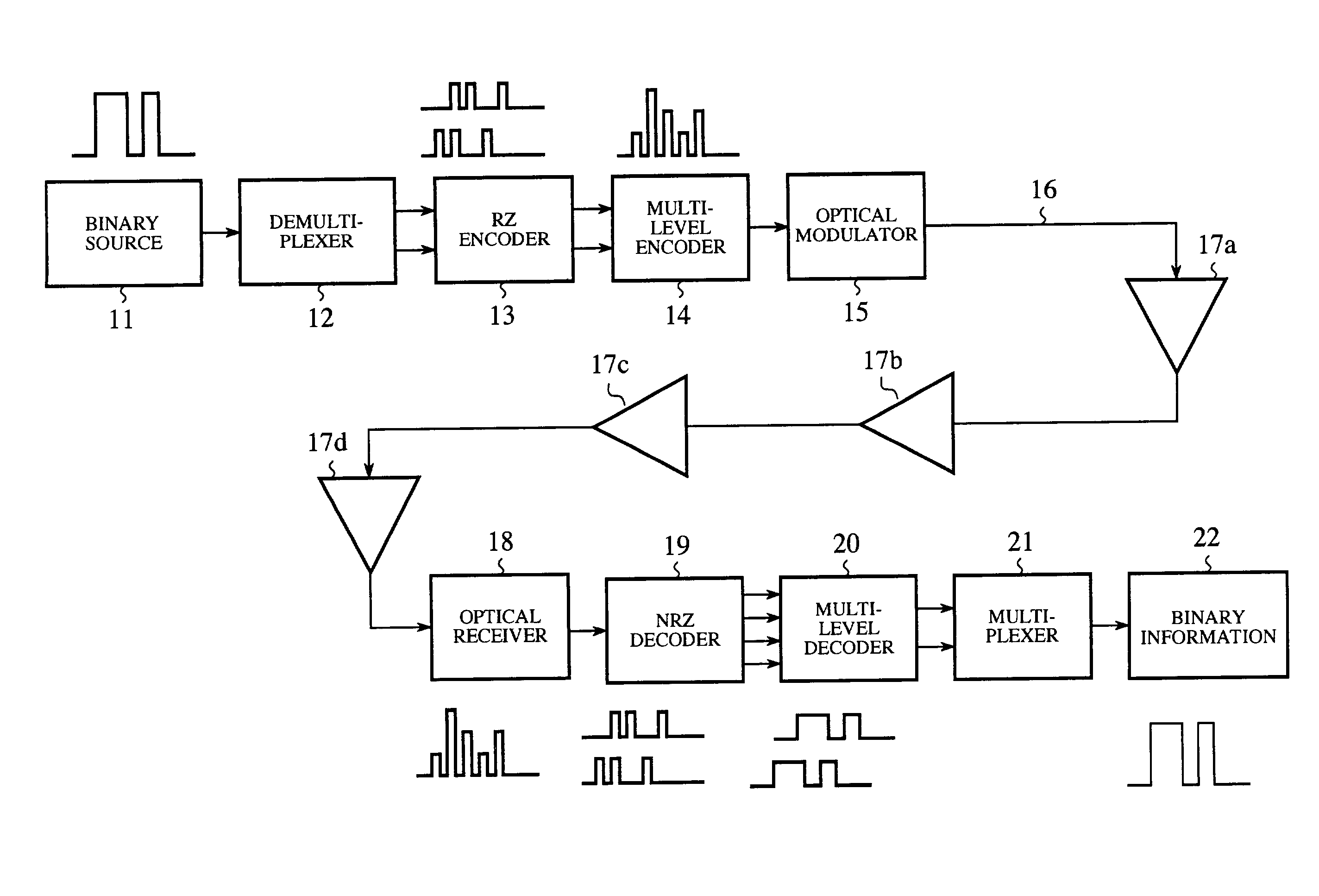
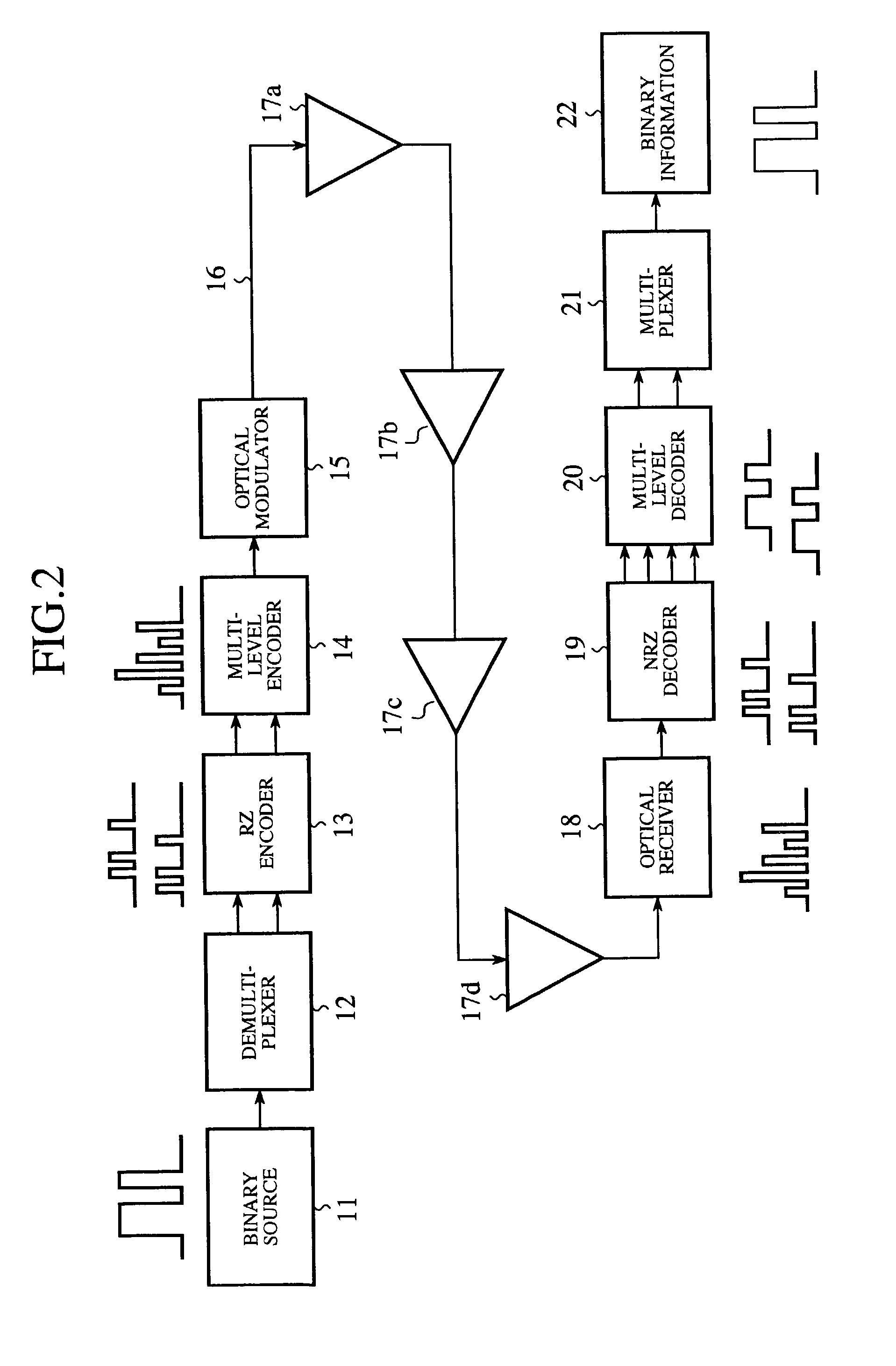
[0050]FIG. 2 illustrates in block form the optical transmission equipment according to Embodiment 1 of the present invention. In FIG. 2, reference numeral 11 denotes binary source for generating binary information; 12 denotes a demultiplexer for demultiplexing the binary information fed from the binary source; 13 denotes an RZ encoder for encoding the binary information demultiplexed by the demultiplexer 12 into an RZ signal; and 14 denotes a multi-level encoder for encoding the RZ signal provided from the RZ encoder 13 into a multi-level signal. The RZ encoder 13 and the multi-level encoder 14 constitute encoding means.
[0051]Reference numeral 15 denotes an optical modulator (modulating means) for performing optical modulation of the multi-level signal fed from the multi-level encoder 14; 16 denotes an optical fiber transmission line; and 17a to 17d denote optical amplifiers. Incidentally, the optical fiber transmission line 16 and the optical amplifiers 17a to 17d constitute transm...
embodiment 2
[0075]While in Embodiment 1 described above the multi-level encoder 14 is placed at the stage following the RZ encoder 13, the multi-level encoder 14 may be provided at the stage preceding the RZ encoder 13, in which case, too, the same results as mentioned above in respect of Embodiment are obtainable.
[0076]Further, in Embodiment 1 the multi-level decoder 20 is placed at the stage following the NRZ decoder 19, but the multi-level decoder 20 may be provided at the stage preceding the NRZ decoder 19, in which case, too, the same results as mentioned above in respect of Embodiment are obtainable.
embodiment 3
[0077]FIG. 5 is a block diagram illustrating the internal configurations of the demultiplexer 12, the RZ encoder 13 and the multi-level encoder 14. In FIG. 5, reference numeral 31 denotes a 1:2 demultiplexer which demultiplexes, by use of a 40 GHz clock, the 40 Gb / s binary information (referred to as 400 Gb / s NRZ data in this case) from the binary source 11 at a 1:2 ratio and outputs two pieces of 20 Gb / s NRZ data. For convenience of description, the one NRZ data will be referred to 20 Gb / s NRZ data (A), and the other NRZ data as 20 Gb / s NRZ data (B). Reference numeral 32 denotes a frequency divider that frequency-divides the 40 Gb / s clock and outputs a 20 Gb / s clock.
[0078]Reference numeral 33 denotes an AND circuit which calculates the product of the 20 Gb / s NRZ data (A) and the 20 GHz clock and outputs 20 Gb / s RZ data (A); 34 denotes an AND circuit which calculates the product of the 20 Gb / s NRZ data (B) and the 20 GHz clock and outputs 20 Gb / s RZ data (B); 35 denotes a 6 dB atten...
PUM
 Abstract
Description
Claims
Application Information