Stereo camera arrangement in a motor vehicle

a camera system and motor vehicle technology, applied in the direction of television systems, instruments, machine supports, etc., can solve the problems of short changes in spacing between the camera modules and the motor vehicle, the inability to adjust, and the inability to use the support. , to achieve the effect of simple and secure assembly, quick change of spacing

Inactive Publication Date: 2006-09-26
ROBERT BOSCH GMBH
View PDF12 Cites 89 Cited by
  • Summary
  • Abstract
  • Description
  • Claims
  • Application Information

AI Technical Summary

Benefits of technology

[0013]In this connection, according to the present invention, rapid, simple and secure assembly is made possible in that the camera modules are first inserted into the mount. For this purpose a snap-in or snap-fit mechanism may for example be provided in the mount for accommodation of the camera modules, in for example their lens region, in order to ensure secure positioning and firm seating. The mount with the camera modules in place is then cemented to the inside of the windshield. These steps may be executed immediately after production of the windshield, for example in the windshield production shops, so that the windshield together with the camera system composed of camera modules and mount can be delivered as one structural unit. After insertion of the windshield into the body, electrical connection of the camera modules, in particular data connection with the control means via a flexible data line, and installation of the cover between windshield and roof region take place.

Problems solved by technology

In such conventional stereo camera systems in a motor vehicle, however, changes in spacing of the camera modules with respect to one another and with respect to the motor vehicle are a problem.
On the other hand, brief changes in spacing, which may for example be injected into the support by vibrations, can generally not be corrected.
However, more rigid design of the support generally results in higher manufacturing costs and a higher total weight and yet fails to provide sufficient suppression of vibrations.

Method used


Image

  • Stereo camera arrangement in a motor vehicle
  • Stereo camera arrangement in a motor vehicle

Examples


Embodiment Construction

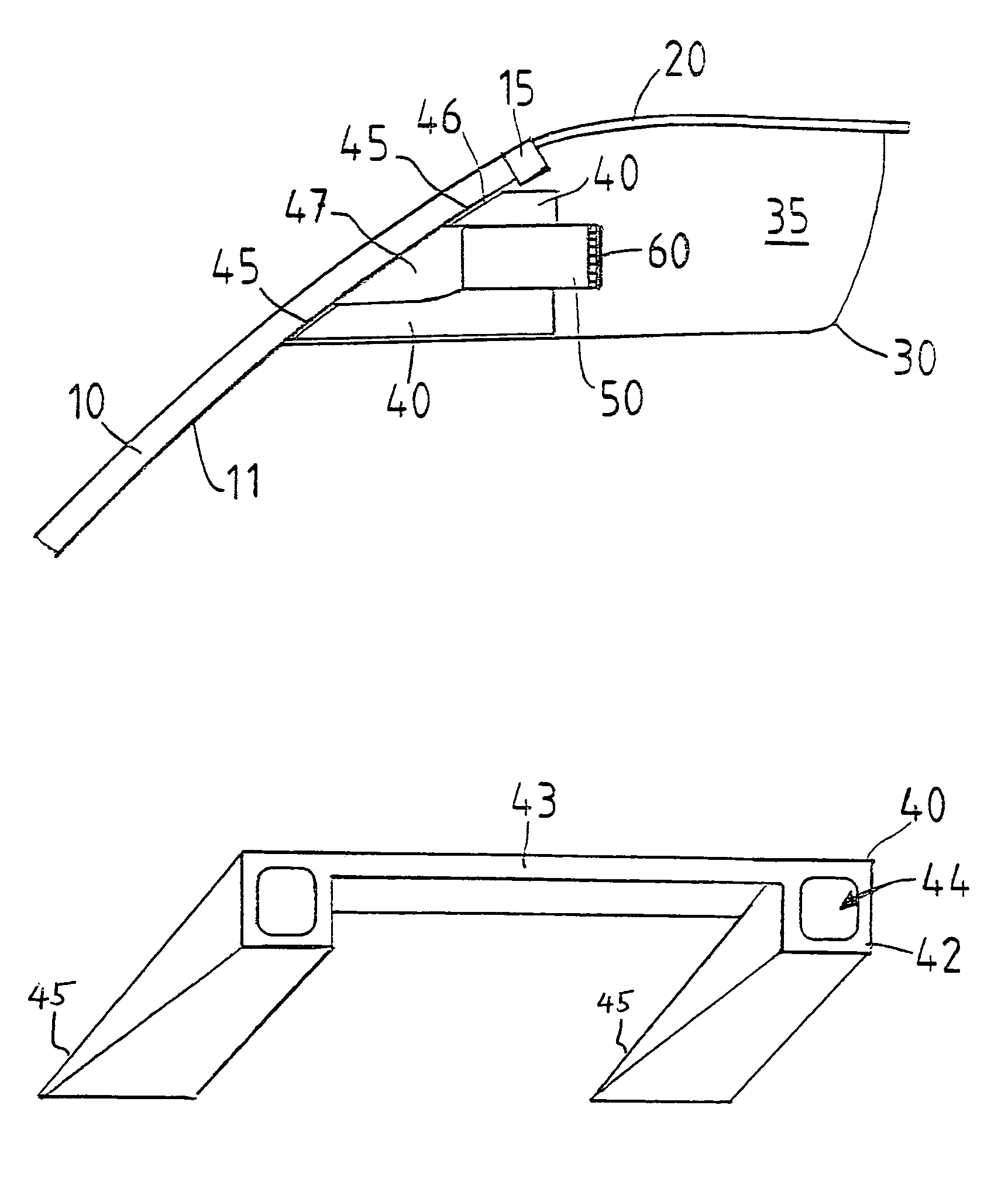
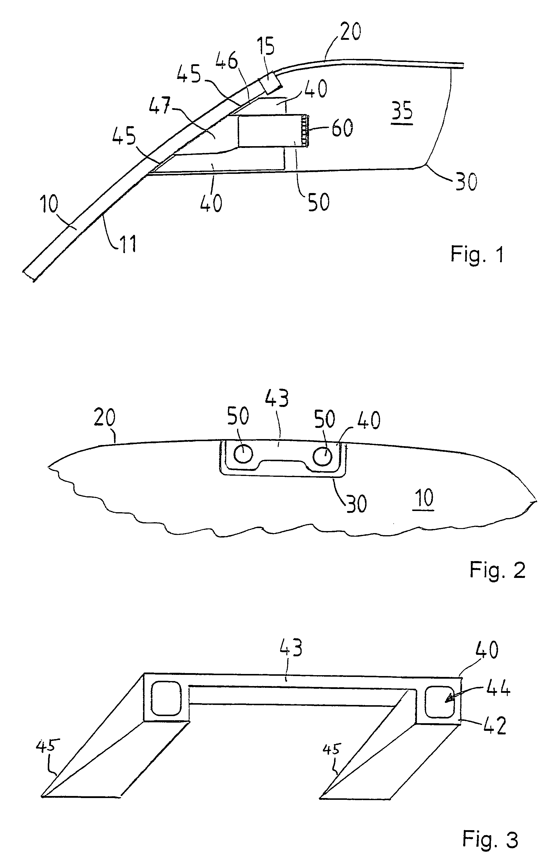
[0017]FIG. 1 shows, as a partial view of a motor vehicle, an upper region of windshield 10, which is connected by a seal 15 with a roof section 20 of the vehicle. A cover 30 is provided between the inside 11 of windshield 10 and roof section 20 and encloses a camera region 35. Provided in camera region 35 is a mount 40, which is fastened to the inside 11 of windshield 10 in cementing regions 45 by a cementing layer 46. According to FIGS. 1, 2, mount 40 does not rest against cover 30. Mount 40 holds two camera modules 50, essentially parallel to one another, at a specified distance apart, a space 47 in front of the lens being formed between each camera module 50 and windshield 10, in order not to influence the optical path in front of the camera modules. Cementing regions 45 advantageously extend annularly about spaces 47, in front of the lenses so that mount 40 covers the camera modules at the bottom and at the sides and thus keeps scattered light away from camera modules 50. Accord...


PUM


Abstract

A stereo camera system in a motor vehicle, in particular for classifying objects and determining distance. In order to ensure secure installation and precise positioning of the camera system, in particular fixing of its lateral position, the camera system is provided with at least two camera modules, and a mount, in which camera modules are installed at a specified lateral distance apart, the mount being cemented to the inside of the windshield.

Description

FIELD OF THE INVENTION[0001]The present invention relates to a stereo camera system in a motor vehicle, in particular for classifying objects.BACKGROUND INFORMATION[0002]Stereo camera systems or stereo front-camera systems (SFK systems), in which two camera modules, generally parallel to one another, which detect the roadway area in front of the vehicle through the windshield, are mounted in the motor vehicle, are used for classifying objects on a roadway, for assigning attributes to objects, and for determining the distance of objects from a motor vehicle. For the required accuracy in determining the distance of contours in the stereo video image for distances greater than / equal to 40 m, the relative positions of the contours must be resolved into the micrometer range on the electronic imaging chips. To do this, the relative positioning of the two cameras to one another must be effected in a very precise and stable manner; in addition, the position of the camera system with respect...

Claims


Application Information

Patent Timeline
Patent Type & Authority Patents(United States)
IPC IPC(8): G03B17/00B60R1/00B60R11/04F16M13/02
CPCB60R11/04H04N13/239
Inventor SEGER, ULRICHAPEL, UWE
Owner ROBERT BOSCH GMBH
Why Eureka
Try Eureka