Robust chemiresistor sensor

a chemiresistor sensor and robust technology, applied in the direction of diaphragms, immobilised enzymes, cells, etc., can solve the problems of reducing sensor performance, film to gradually separate from the terminal, and volumetric change of film

Inactive Publication Date: 2006-09-26
THERM O DISC
View PDF38 Cites 8 Cited by
  • Summary
  • Abstract
  • Description
  • Claims
  • Application Information

AI Technical Summary

Benefits of technology

[0008]The present invention improves upon the prior art by providing a chemiresistor sensor probe having a first control surface and a second control surface that permit control over the thickness of the sensor film. Recessed within the first control surface is the second control surface. The sensor film is disposed upon the second control surface and does not extend beyond the first control surface. The thickness of the sensor film is equal to the distance that the second control surface is recessed within the first control surface, thus permitting the thickness to be controlled by varying the distance that the second control surface is recessed within the first control surface.

Problems solved by technology

The polymer absorbs target analytes and this results in a volumetric change of the film, and hence the electrical resistance of the film.
Specifically, as the volume of the sensor film expands and contracts over time in response to the presence of the target analytes, the mechanical bond between the sensor film and the terminals is weakened, thus causing the film to gradually separate from the terminals.
This weakening of the electrical bond between the film and the terminals decreases sensor performance because it diminishes the ability of the processor to analyze changes in the resistance of the film through the terminals.
Conventional chemiresistor sensors are also deficient in that they fail to provide a sensor probe having a sensor film of a controlled thickness.
Specifically, the use of a thick sensor film is undesirable because thick films require an extended period of time to absorb the target analyte, thus increasing the time required for the sensor film to swell and produce a change in resistance indicating the presence of the target analyte.
However, the use of a sensor film that is overly thin is also not desirable because excessively thin films are not durable, are difficult to manufacture, and are unstable.
Additionally, a build-up of dirt or surface moisture may contaminate the terminals of conventional sensor probes, causing the sensor to produce inaccurate readings.
This bypass resistor typically desensitizes the performance of the sensor.

Method used


Image

  • Robust chemiresistor sensor
  • Robust chemiresistor sensor
  • Robust chemiresistor sensor

Examples


Embodiment Construction

[0020]The following description of the preferred embodiments is merely exemplary in nature and is in no way intended to limit the invention, its application, or uses.

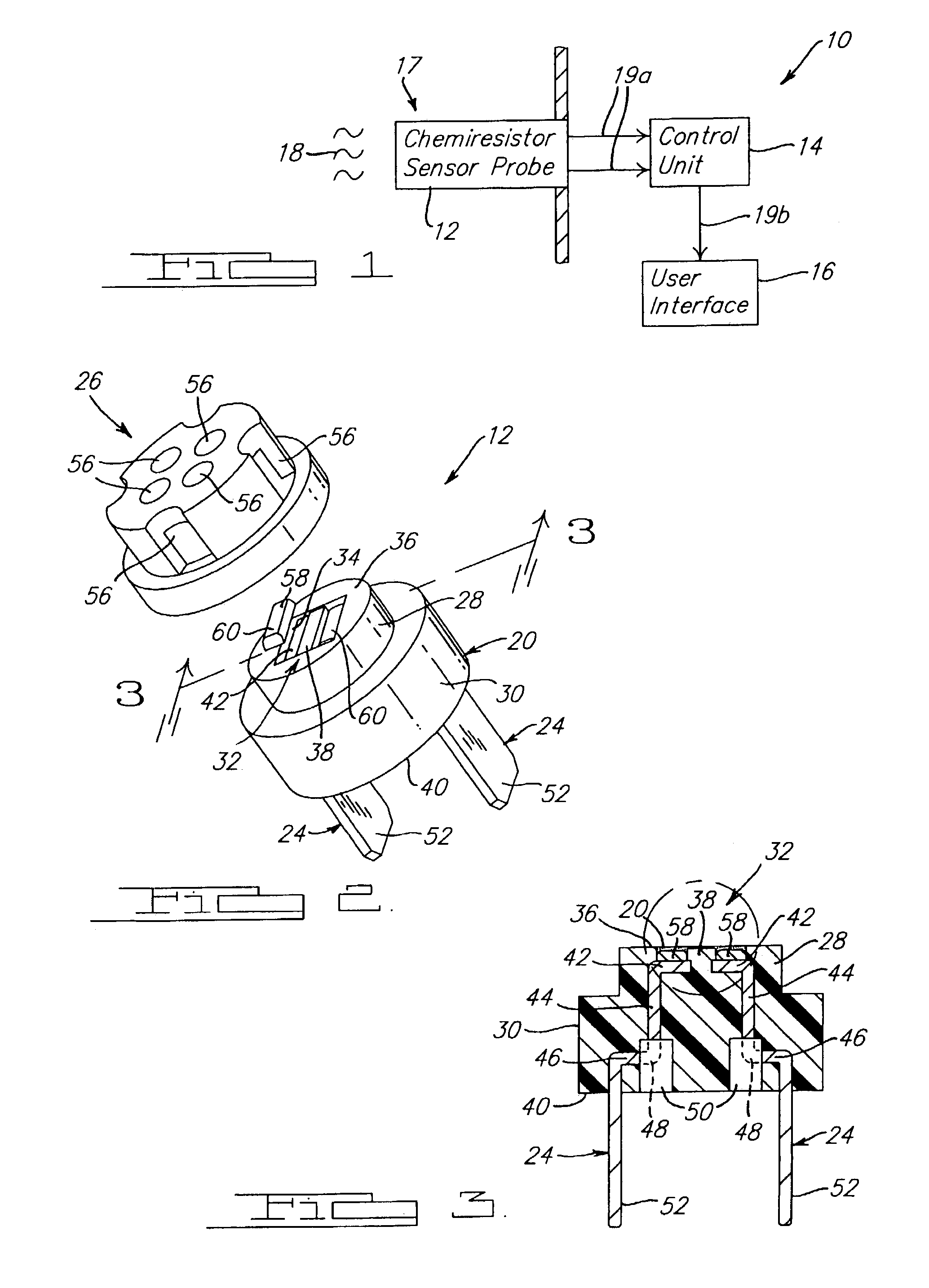
[0021]FIG. 1 generally depicts the major components of an exemplary chemiresistor sensor at 10. The sensor 10 is generally comprised of a chemiresistor sensor probe 12, a control unit 14, and a user interface 16. The sensor probe 12 interacts with an external environment 17 to detect the presence of analytes, or target chemical compositions 18. The sensor probe 12 generates a raw output signal 19a based on continuous detection of analytes 18 in the external environment 17. The raw output signal 19a is processed by the control unit 14. The control unit 14 transmits a calculated output signal 19b to the user interface 16 to relay analysis of the raw output signal 19a from the sensor probe 12. The user interface 16 provides information to an external user about the sensor 10 and may range from a simple alarm signal to a co...


PUM

PropertyMeasurementUnit
conductiveaaaaaaaaaa
resistanceaaaaaaaaaa
thicknessaaaaaaaaaa

Abstract

A chemiresistor sensor probe for detecting target analytes. The probe includes a body having a first control surface and a second control surface recessed within the first. A sensor film comprises numerous conductive particles disposed upon the second surface. The film swells upon absorbing one or more analytes for which it has an affinity, thus causing the conductive particles to become more dispersed and increasing the resistance between the particles. The thickness of the film is equal to the distance between the first surface and the second surface, thus permitting the thickness to be controlled by varying the distance between the control surfaces. The robustness of the sensor probe is enhanced by placing a porous or mesh electrode along with, or in place of, a chemical binding agent between the film and the terminals. The robustness is also improved by placing a diode in series with the sensor circuit.

Description

FIELD OF THE INVENTION[0001]The present invention generally relates to chemiresistor sensors. In particular, the present invention relates to a chemiresistor sensor probe having a sensor film that detects target analytes.BACKGROUND OF THE INVENTION[0002]Detection of specific target analytes, or chemical compounds, is important for many applications, including for example, detecting whether the concentration of analytes exceeds flammability limits. Target analytes are detected by sensors operating according to different detection mechanisms, known in the art. Most sensors employ a sensing component that is physically modified in the presence of specific analytes present in the environment. Thus, a sensor typically comprises a probe that includes both the sensing component and a probe body housing (including terminals for transmitting an output). The terminals are typically coupled to a processor, also part of the sensor, which analyzes the outputs received from the sensor probe. Such...

Claims


Application Information

Patent Timeline
Patent Type & Authority Patents(United States)
IPC IPC(8): B32B5/02B32B27/04B32B27/12G01N21/00G01N7/00G01N27/04G01N27/06G01N27/12
CPCG01N27/125Y10T29/41Y10T29/49002Y10T29/49
Inventor STARLING, JAREDKHADKIKAR, PRASAD S.STERKEN, ROBERTVOLZ, CHARLES L.BLOK, EDWARD J.DONNELLY, DONALD E.
Owner THERM O DISC
Why Eureka
Try Eureka