Composite lock for computer systems with multiple domains

a computer system and domain technology, applied in computing, instruments, electric digital data processing, etc., can solve problems such as serious problems, cpu power, and computation cycles, and achieve the effect of limiting factors, preventing cpus from changing linkings, and limiting factors

Active Publication Date: 2006-10-03
VMWARE INC
View PDF4 Cites 99 Cited by
  • Summary
  • Abstract
  • Description
  • Claims
  • Application Information

AI Technical Summary

Problems solved by technology

As the number of tasks increases, however, the point may be reached where computational cycles, that is, CPU power, is the limiting factor.
A serious problem may arise, however, if both tasks 1 and 2 execute these programs concurrently: Suppose the balance starts at 1000; Task 1 is depositing 100 dollars, while Task 2 is withdrawing 100 dollars.
This program “races,” since, as in a foot race, one cannot know what the result will be until the race is run.
For example, one of the CPUs cannot be allowed to change the linkings of a doubly linked list while the other CPU is traversing the list.
This would certainly be sufficient to correct problems like the bank balance example above, but the cost would in most cases be too great: By ceding too much control to applications, a faulty or malicious application would be able to monopolize the system and prevent other tasks from running.
Moreover, this would not even allow one to take advantage of the capabilities of a true multi-processor system.
This is because interleaving of these deposit and withdrawal instructions could cause ambiguous results.
One property of a lock is that two consecutive LOCK operations (with no intervening UNLOCK operation) cannot be allowed to succeed.
Spin locks have the disadvantage, however, that waiting tasks use CPU time (executing their loops) that could be used to do useful work.
Blocking locks present the opposite set of trade-offs to those of spin locks: They have the advantage of not wasting CPU time while waiting for long-held locks, but they have

Method used


Image

  • Composite lock for computer systems with multiple domains
  • Composite lock for computer systems with multiple domains
  • Composite lock for computer systems with multiple domains

Examples


Embodiment Construction

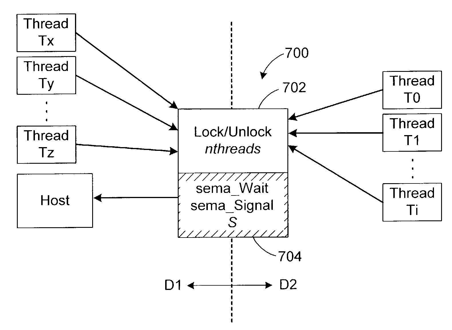
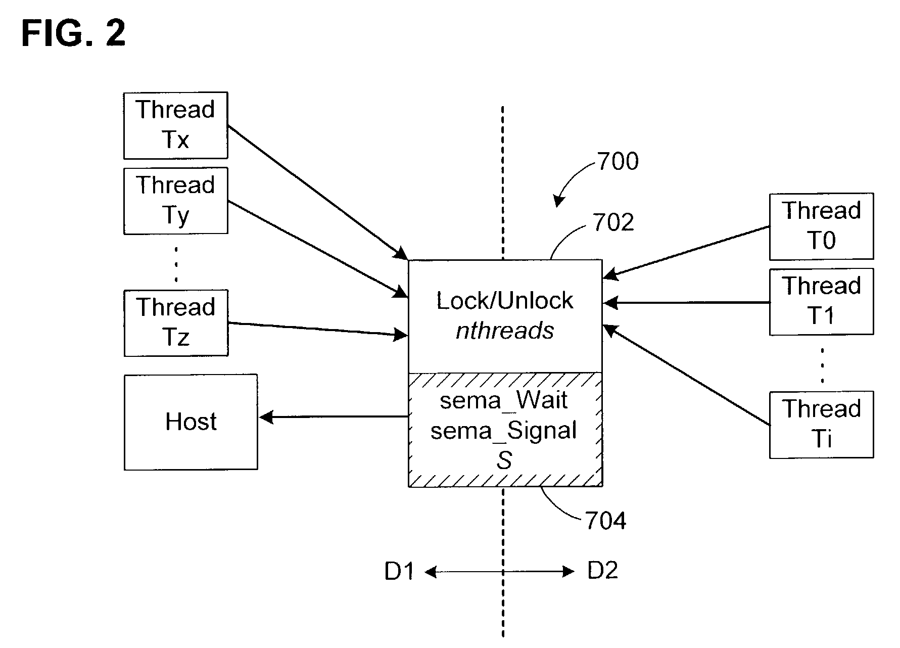
[0070]In a system in which concurrent threads require mutually exclusive access to a resource, the invention provides a domain-crossing, composite lock with a platform-independent lock component and a conventional, platform-dependent lock component. The only assumption concerning the platform-dependent lock component is that it operates as a semaphore, such as is provided by all common OSs.

[0071]The invention is particularly advantageous where the concurrent threads run in different domains, although this is not required by the invention. The two lock components also operate across the different domains. In cases where the lock according to the invention is uncontested, proper, mutually exclusive concurrency can be provided by the composite lock without performing any domain crossings. In the remaining cases, when there is a need to transition between lock components, and thus domains, the invention detects this need rapidly, although the overall cost will often be dominated by the ...


PUM


Abstract

In a multi-domain computer system in which several processes are running, a composite lock provides mutually exclusive access to a resource. The composite lock has a back-end component and a front-end component. The back-end component is platform-dependent and operates as a semaphore, with Wait and Signal functions. The front-end component conditionally calls the Wait and Signal functions depending on whether the lock is currently contested when a new process wishes to acquire the lock, and on whether any process is currently suspended, waiting to acquire the lock. The front-end and back-end components may execute in different domains. In the uncontested case, the invention avoids costly domain crossings. The front-end component may also include a spinning feature to further reduce the need to invoke the back-end component and cause a domain crossing. The composite lock is particularly advantageous in computer systems that include a virtual machine.

Description

BACKGROUND OF THE INVENTION[0001]1. Field of the Invention[0002]This invention relates to the coordination of concurrently running processes in a computer.[0003]2. Description of the Related Art[0004]Most personal computer systems are equipped with a single processing unit (CPU). Because CPUs today are quite fast, a single CPU often provides enough computational power to handle several “concurrent” tasks by rapidly switching from task to task (a process sometimes known as time-slicing or multiprogramming). This management of concurrent tasks is one of the main responsibilities of almost all operating systems.[0005]Two main concepts in concurrent programming are “processes” and “resources.” A process is a sequence of executable code with its own thread of control. Concurrent programs are distinguished from sequential programs in that they permit multiple, simultaneous processes. Processes may share resources; examples of sharable resources include software resources such as data stru...

Claims


Application Information

Patent Timeline
IPC IPC(8): G06F9/45
CPCG06F9/526
Inventor AGESEN, OLEADAMS, KEITH M.
Owner VMWARE INC
Why Eureka
Try Eureka