Bits for use in drilling with casting and method of making the same

a technology of drilling and casting, applied in the direction of drilling machines and methods, cutting machines, constructions, etc., can solve the problem of less than 100 percent coverage of the design of the bit, and achieve the effect of economic manufacturing

Inactive Publication Date: 2006-10-10
WHEELER JAMES L +1
View PDF1 Cites 35 Cited by
  • Summary
  • Abstract
  • Description
  • Claims
  • Application Information

AI Technical Summary

Benefits of technology

[0009]In accordance with the present invention, a bit for use in drilling a borehole using completion casing or the like in a single run is provided. The purpose of the bit of the present invention is to provide for such a bit that is economical to manufacture, is effective in drilling shallow to medium depth formations while casing and can be cemented in a borehole along with the casing. The bit is not intended to be retrieved after drilling of the borehole, and the bit is manufactured from a material which does not allow the bit to be readily drilled.
[0011]The cutting face includes at least one cutting blade extending radially therefrom. The cutting blade includes a cutting face which is adapted to receive cutter inserts, such as Polycrystalline Diamond Cutting (PDC) inserts, Tungsten Carbide (TC) inserts, Synthetic Diamond Impregnated Sintered Carbide Disks or the like. The cutting face may also be adapted to receive TC post type PDC cutters. The cutting blades also include gauge pads that are integrally formed therewith and they can be either straight or sweep-type gauge pads. The cutting faces of the blades can also use external hard metal deposition cutting faces. Preferably, three blades are used and have a blade spacing of approximately 120 degrees radially around the cutting face. The number and position of the blades can be at least one to as many as will fit along the profile and diameter of the bit. The use of three blades provides for optimization between stability of cutter position balanced with minimal coverage.
[0012]Minimal coverage, is defined as the minimum number of cutter inserts used to provide approximately 100 percent of the bottom hole surface area contact with the cutter inserts as they are rotated about the central axis of the bit. Normally, a bit that incorporates cutter inserts is designed for multiple runs in both soft shallow and medium depth harder formations. The cutter inserts therefore are spaced to reduce the amount of cutting each insert provides, thereby increasing cutter life. The bit of the present invention is designed to optimize cutter life to a single run. A few of advantages of optimizing cutter life of the bit of the present invention to a single run is found in providing for higher rates of penetration (ROP) through higher cutter loading and by providing reduced bit structure which increases manufacturing efficiency and reduced cost. However, it should be recognized that while minimal coverage bit design is most desirable, less than 100 percent coverage bit design could be used.
[0015]The unique manufacturing technique of the present invention is employed to produce the bit body's integrated female non-shouldered, standard oilfield completion string thread without the problem of eccentricity or egging of the thread. A two-step procedure is used to finish the body's blade structure before the threads are machined. The process involves, first initializing a bit blank with an inner straight bore having two concentric bores at different diameters to facilitate mounting the blank on a matching profile jig. The jig is mounted to a milling machine and the bit's outer blade geometry is machined. The diameters of the jig and the blank bore are closely toleranced to provide the needed stability in machining the blade geometry. The bit blank body thickness is much higher than when finished to prevent the body from deformation that would otherwise result from internal stress resulting from the milling operation.

Problems solved by technology

The bit is not intended to be retrieved after drilling of the borehole, and the bit is manufactured from a material which does not allow the bit to be readily drilled.
However, it should be recognized that while minimal coverage bit design is most desirable, less than 100 percent coverage bit design could be used.

Method used


Image

  • Bits for use in drilling with casting and method of making the same
  • Bits for use in drilling with casting and method of making the same
  • Bits for use in drilling with casting and method of making the same

Examples


Embodiment Construction

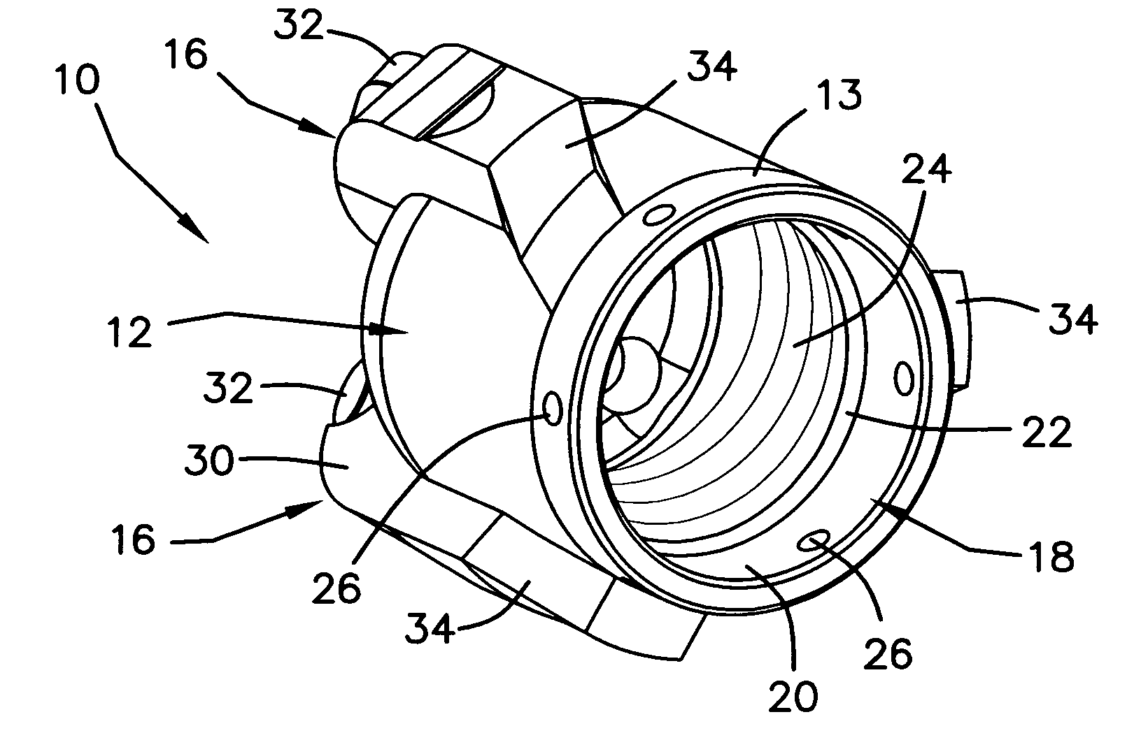
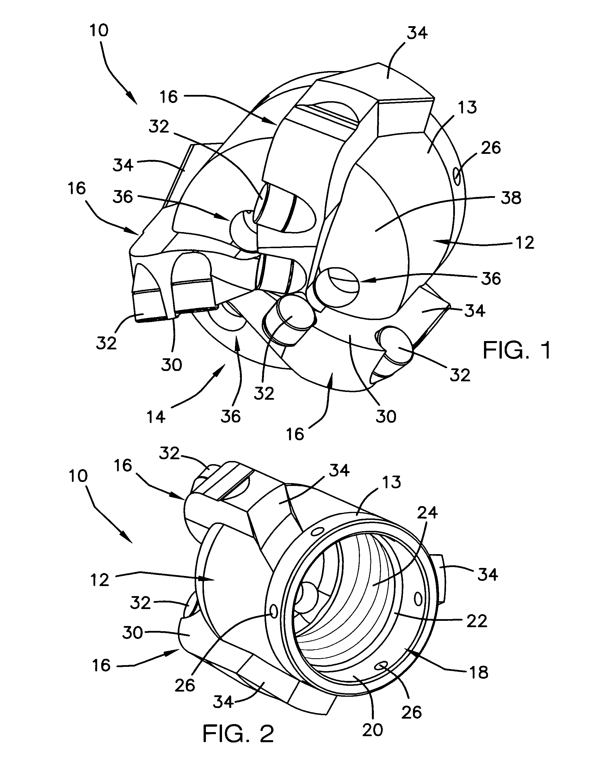
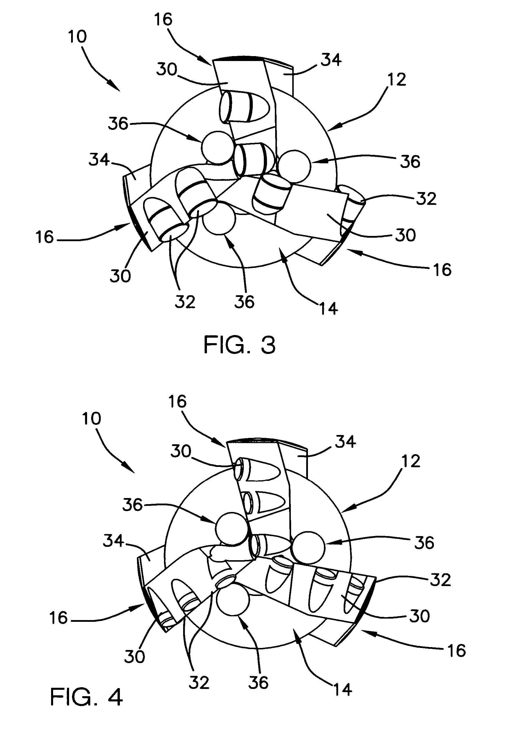
[0030]Referring now to the drawings, and particularly to FIGS. 1–3, a preferred embodiment of the bit that can be used for drilling while casing of the present invention is shown and generally designated by the reference numeral 10. Briefly, the bit 10 is referred to in the art as a drag bit or fixed cutter bit and is intended to be economical to manufacture, effective in drilling shallow to medium depth formations while casing and can be cemented in a borehole along with the casing. The bit 10 is not intended to be retrieved after drilling of the borehole, and the bit is manufactured from a material which does not allow the bit to be readily drilled.

[0031]The bit 10 is designed to be used with a standard well completion strings and used for drilling a borehole using the completion string as a drill string. In use, the bit 10 is fixed to the leading end of the completing strings using a standard female thread and is rotated with the string using a rotation platform positioned above ...


PUM


Abstract

Bits for use in drilling with a well completion string having a bit body and a cutting face that includes a plurality of sets of cutter elements mounted on the cutting face. The bit body has a central longitudinal bore having an integrated female non-shouldered, standard oilfield completion string thread. The bits are designed with minimal cutter coverage, and this combined with the integrated completion string thread allows for economical completion of a well with high ROP expected from a PDC type bit. In an additional embodiment, a bit comprises a bit body and a cutting face having integrated cutting structures.

Description

CROSS-REFERENCE TO RELATED APPLICATION[0001]This application claims the benefit of U.S. Provisional Application No. 60 / 523,144, filed Nov. 19, 2003.BACKGROUND OF THE INVENTION[0002]1. Field of the Invention[0003]The present invention relates generally to fixed cutter bits of the type used in cutting geological formations such as used in drilling a borehole for completing an oil well or the like. More particularly, the invention relates to fixed cutter bits for attachment to a well casing for effecting simultaneous drilling and casing of a borehole.[0004]2. Description of the Prior Art[0005]In drilling a borehole through a formation it is normal procedure to connect a drill bit on the lower end of an assembly of drill pipe sections which are connected end-to-end so as to form a drill string. An apparatus that is positioned above the surface of the borehole rotates the drill string. The apparatus turns the drill string and advances it downwardly, causing the bit to drill through the f...

Claims


Application Information

Patent Timeline
Patent Type & Authority Patents(United States)
IPC IPC(8): E21B7/20E21B10/54E21B10/55
CPCE21B7/20E21B10/55
Inventor WHEELER, JAMES LKAPP, ROBIN W
Owner WHEELER JAMES L
Why Eureka
Try Eureka